My quest for the fakest Commodore 64 possible!
My relationship with the nature of things is a strained one at times, a strange one at others. What makes a thing the thing it is anyway ? I'm not going into that right now, I promise.
But the title of this project begs an explaination! The most fake c64? That would be an emulator. I decided that a C64 has to have a physical component to it, something a bit more electrical in nature. So, in my definition, it is a machine which acts exactly like a C64 and replicates and responds to its actual electrical signals in real time, both to the outside world through various connectors, and also represents the electrical interconnections found in the real hardware.
I thought that the Ultimate64 was a C64, but decided that it was not, the cartridge port is not compatible.
A C64 is roughly made up of
bwack made a really awesome tool, an interactive BOM that lets you explore the motherboard.
| Function | Original | Replacement |
| ✅ Motherboard | ASSY 250407 (C)1983 | Sixtyclone ASSY 250407 2021 |
| ✅ CPU | MOS 6510 | UMC UM6502A in MOS CPU Replacer |
| ✅ Graphics | VIC-II (MOS 6569R1) | Kawari |
| ✅ Sound | SID (MOS 6581) | ArmSID |
| ✅ Glue logic | PLA (MOS 906114-01) | GAL-PLA |
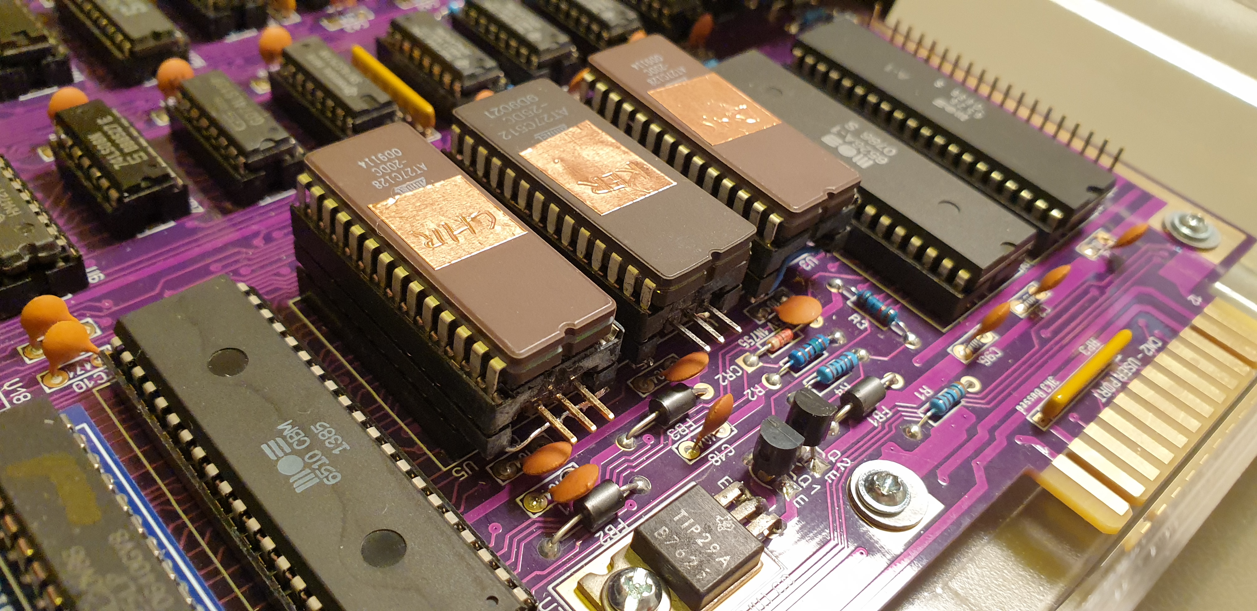
| ✅ CHARGEN ROM | MOS 901225-01 | Atmel AT27C128-20DC in socket adapter |
| ✅ BASIC ROM | MOS 901226-01 | Atmel AT27C128-20DC in socket adapter |
| ✅ KERNAL ROM | MOS 901227-03 | Atmel AT27C512-25DC in socket adapter |
| ✅ Case | C64c case | Newly produced transparent C64c case |
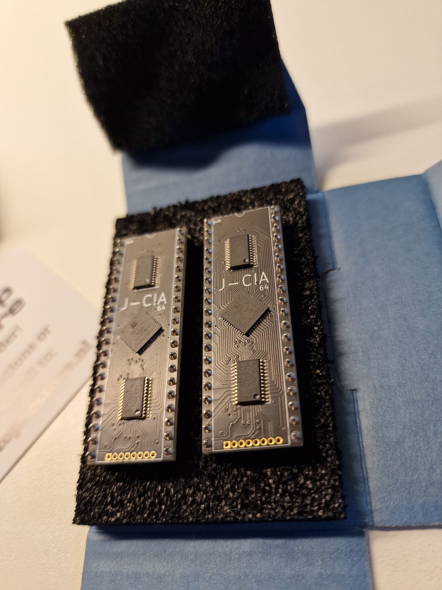
| ✅ IO/Serial/Timer | CIA (MOS 6526A) | J-CIA |
| 🕑 Keyboard | Original C64 keyboard | Todo: Mechboard 64 + adapters + new keycaps |
I'll explain the details of each component further down, but first, a short "work log".

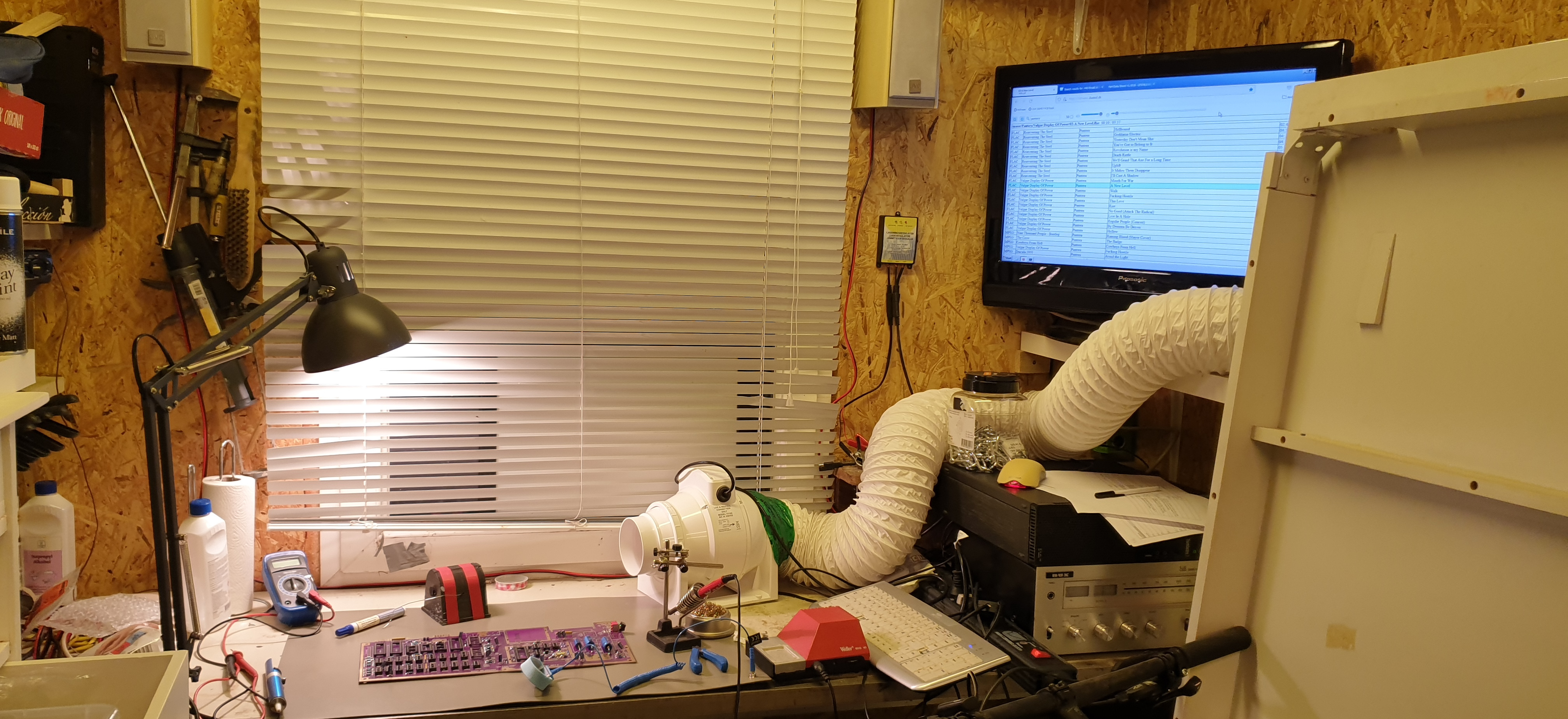
Most of the project took place in my shed, I used the following tools, more or less:
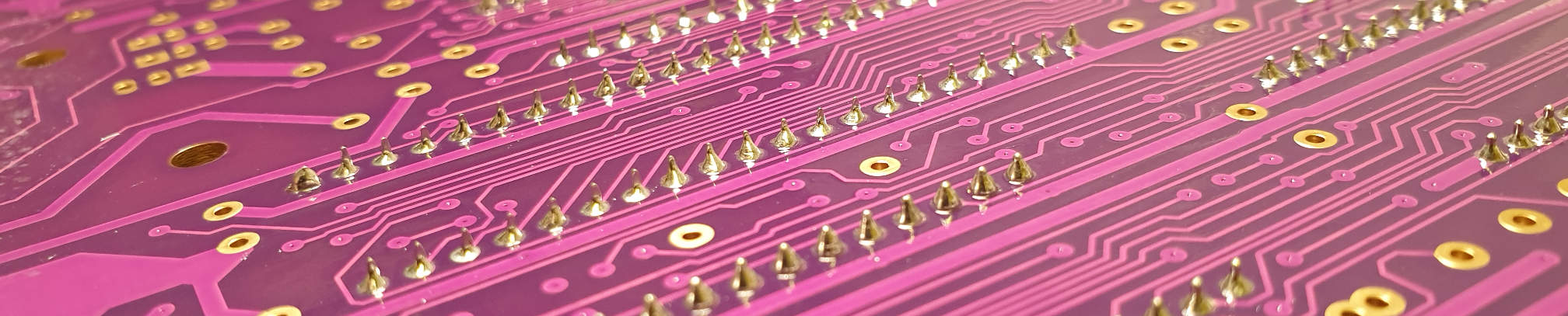
I started out by putting in all the sockets, they are mechanically strong so they will take most of whatever "handling abuse" comes, they are also low-profile so they won't block installation of the other components.

I use sockets for all the ICs, they have the downside that they may "pop" the chips up in time, which requires you to re-inser the chip by pressing on it, on the other hand they allow you to replace chips without soldering, a big plus for maintenance and hacking.
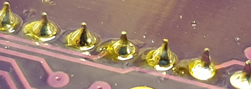
After soldering, there will be flux residue on the board. I assembled this in a few evenings after work, and I cleaned the board carefully with Isopropyl and the toothbrush after each session. Some flux is supposed to be "no clean" menaing you can leave it on there, but I don't want it there, it does not look nice, however this roll of solder is ancient and is likely not "no clean" anyways.
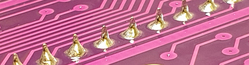
After cleaning, big difference.
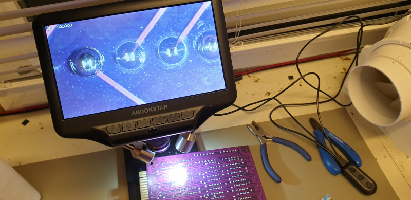
At my age (lol, I'm not even 40 yet..) I am noticing my optical resolution not being what it used to, so I bought a cheap microscope from china, it's totally awesome for stuff like checking that you actually did what you think you did (not shorting stuff out), not so relevant on a c64 project, but on SMD stuff and for inspecting, it's both fun and useful!
Due to the solder containing lead, I used nitrile gloves when handling the board and when soldering, and the fume extractor running always. I know the smell of solder well from a slighty undersupervised childhood, I can tell for sure, the fume vented _EVERYTHING_ to the outside.
After installing all sockets and components except a few connectors and the ICs.
I did two smoketests, the first after installing all the small stuff, resistors, regulators, caps, diodes and transistors, I measured a perfect 5.01 volt on the internally regulated 5v trail, and 5.1 on from the Electroware, however, this is without load and with the long cable, it will be fine. The unloaded 9v AC was about 10v and the 12v was 12.00. Also, no smoke.

Notice the lovely brackets for holding the keyboard, bought them from the same place I bought the case.
Ready for the second smoke test, all chips installed, regulators heatsinked, TV connected.
I figured it'd not work when I powered it up, so I built a "dead test" cartridge that would work even without working firmware ROMS.
The PCB actually had a wrong resistor value on an address pin which prevented it from working, so I shorted that to GND and continued.
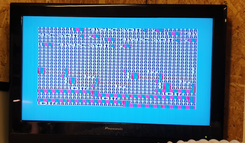
Not a single smoke! Okay, strange.. I tested the cartridge in a working machine, it.. worked, the color scheme is from that cartridge!
After a bit of searching, I found it problem!
I should digress here, and say that, for all the generic parts, I ordered more than I needed, always at least +1, lucky!
They sent me a wrong part number! One of the chips, the U14, supposed to be a 74LS258, they sent me something else, threw it away, forgot the number.
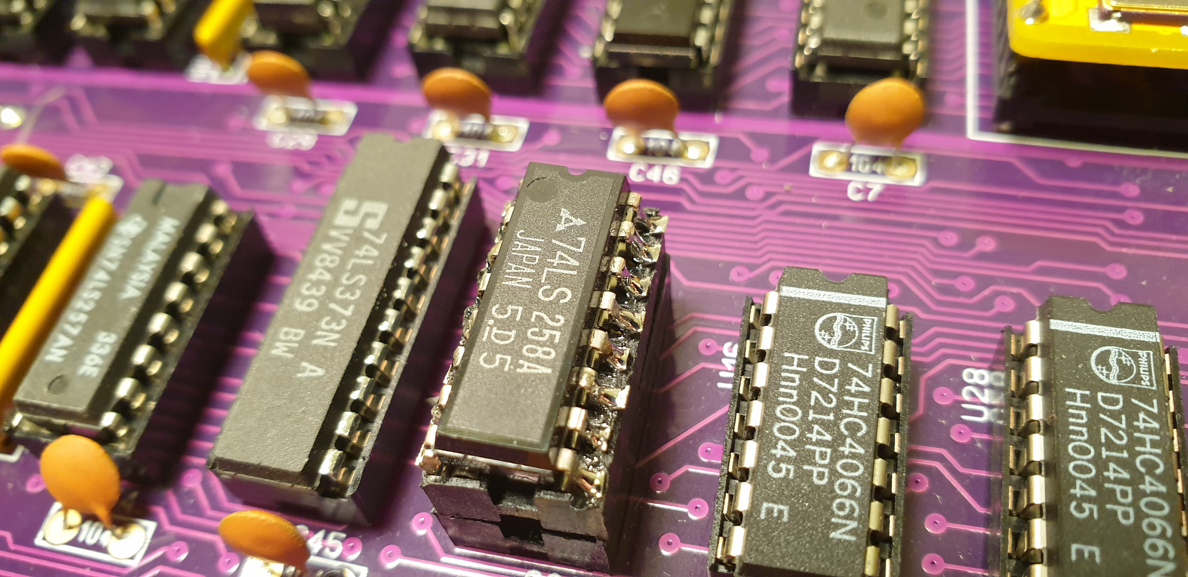
So I though I was screwed, and they'd picked two wrong chips for me, so I snipped one from a working machine (the disgrace!) and soldered it into a socket.
I didn't want to risk overheating or breaking it during desolder, that's why I clipped the pins, least stressful, and soldering it into another socket is also a very gentle process, and I of course cleaned the original PCB and installed a socket so it could come back home.
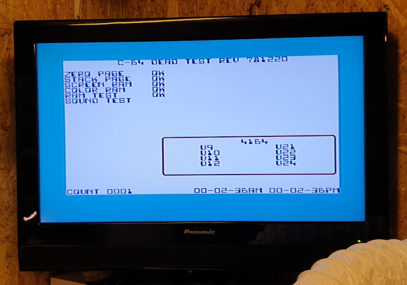
That's all it took, booted up and everything checked out, almost dissapointing that the only two things I had to debug were a dead-on-arrival cartridge PCB and a wrongly picked part.
But wait, there's more! The 74LS258 got to return home! Because remember I told that I ordered +1 of everything.. Guess what, they sent two different chips! A wrong and a right one! The right one, it worked!

The PSU is made by Electroware, I kind of regret not having built it myself, but doing that in the future is an open option, just because.. But for now, it's just an off the shelf one (how cool is it that you can buy off-the-shelf replacement PSUs for a C64 in 2022??).
Someone bought the original molds for the C64c cases and made some production runs, I got one from icomp.de, they flat out refused that there was a problem with shrinkage and cracking, but other than that, I don't want to complain, I got the stuff I ordered and in a timely fashion.
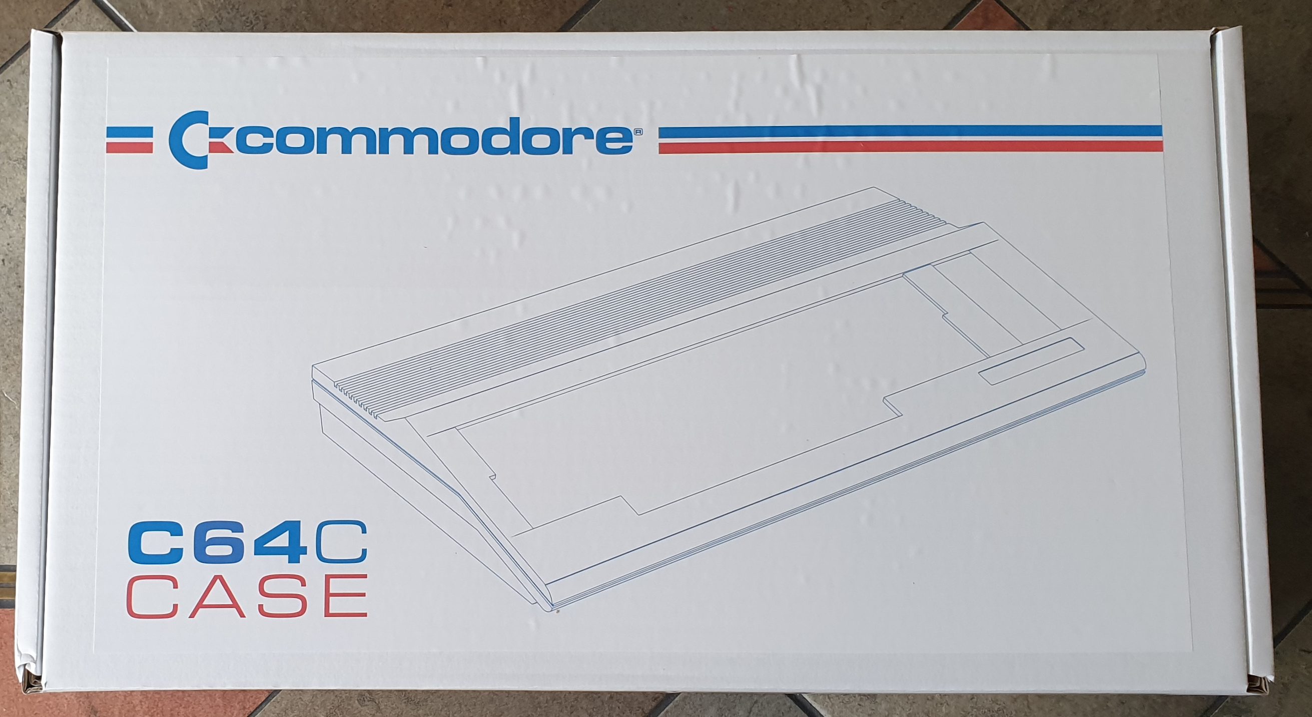
It comes in a sturdy enough cardboard box. Even getter, inside the box is a brand-new C64c case!
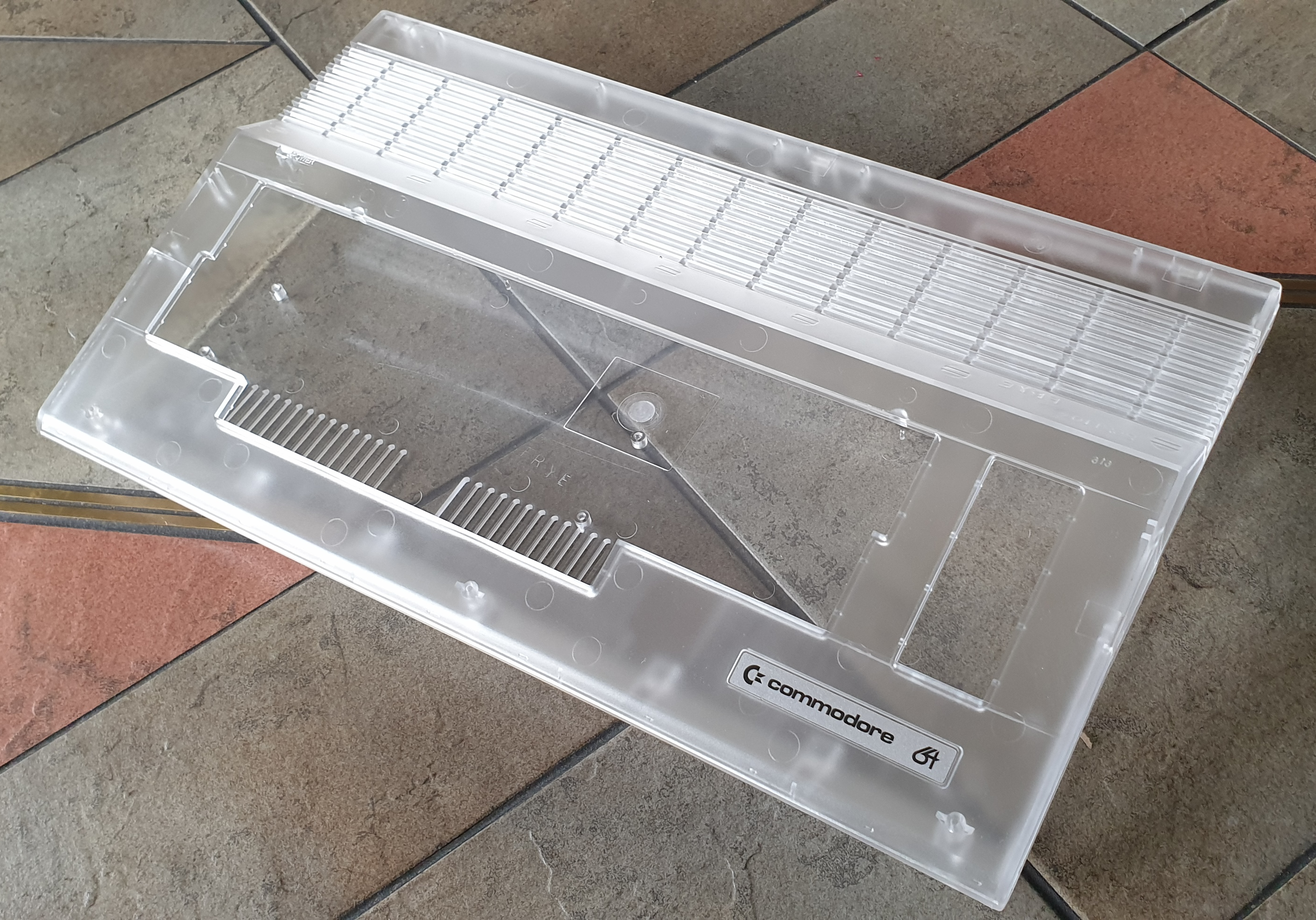
I got the clear case, which looked really great when I took it out of the box. The left side instantly cracked. It seems VERY fragile, even compared to original 40 year old ones. It is also not the _exact_ same size as the original case. It is about 1mm more narrow, making it difficult to fit the motherboard. More on that later.
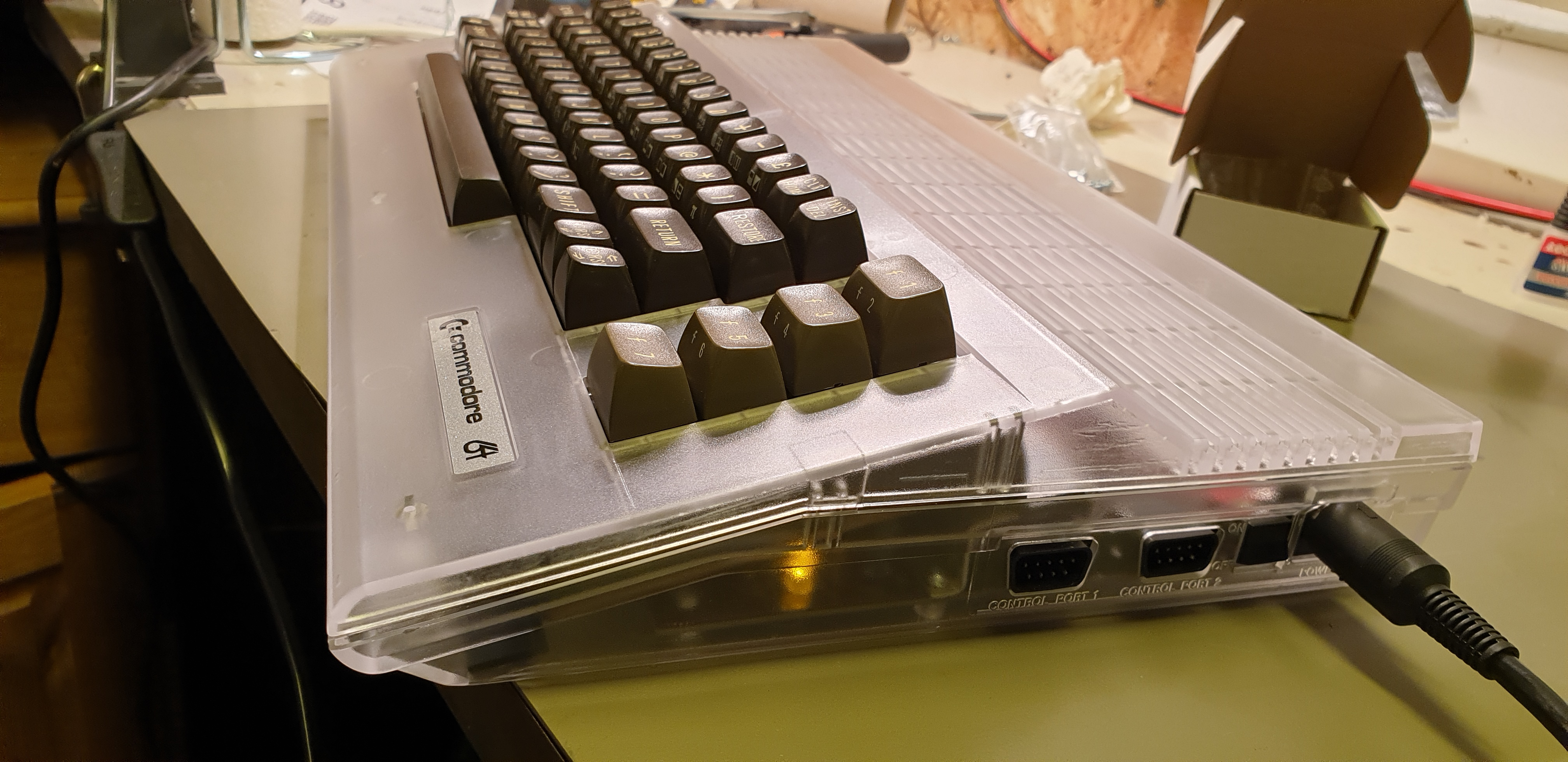
Did you notice I didn't place a pinheader for connecting the power LED? I just plopped a yellow LED in there? This is why. The clear case makes it look very subtle and cool, and frees my top-facing LED for other interesting uses, and it's one run of wire less, always great!
This is still "todo", I'm currently using a keyboard from an C64, but I want to build a Mechboard64 at some point.. All new keycaps, switches, PCB, and metal backplate.
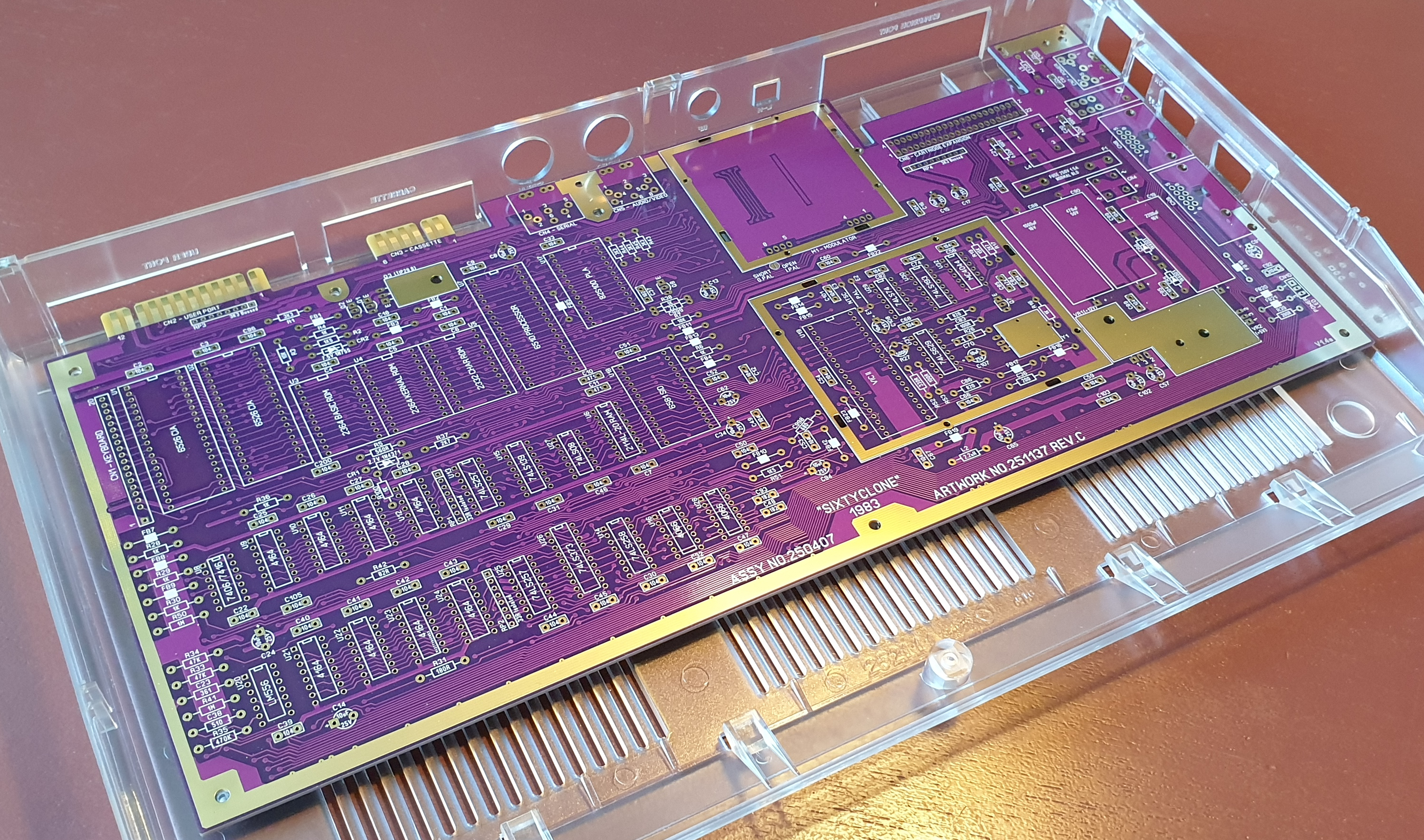
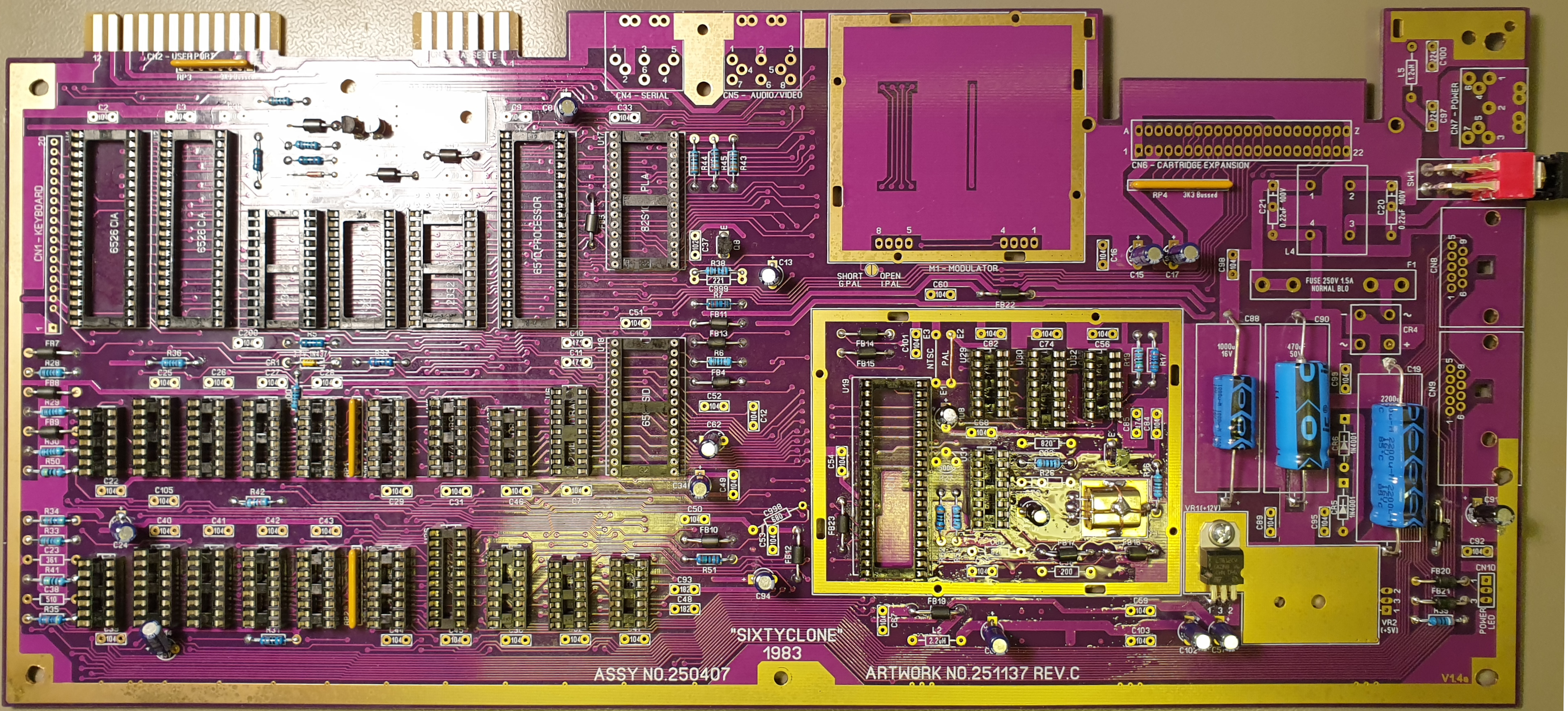
Rob Taylor reverse-engineered and replicated the original C64 mainboards. For this project, I chose the "ASSY 250407". I think it's most aesthetically pleasing board. It's large, and the fewest "C64 specific" chips, and the generic chips are still available today (at least as new old stock).
Ah yes, about the shrinkage, this motherboard is SPOT ON, it's exactly the same dimensions as the original boards, and the scew holes are the same size too (more or less), but I had to take a drill to it, to make it fit into the case..
I chose to "scrape" to one side rather than use a larger drill bit, I did this to preserve the through-hole plating at least partially, there were no vias there on the original board, but more coherent groundplanes never hurt anybody.
Due to the ugly drill holes being visible under the screws, I decided to use washers under each screw, looks okay, for what a hack it is..
I bought these mainly on mouser.
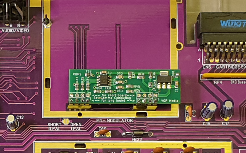
The TV modulator box is rather generic as well, but I decided not to add it, and instead use a by-pass circuit.
The RAM are generic 1 x 65535 DRAM and are new old stock, I consider replacing them with a modern SRAM chip, if nothing else, because the modern chip will be more durable in the long run, this only requires a gate, a 8 bit wide latch and an sram chip, but someone already made this kind of adapter board, and I consider strongly simply buying a premade one.
I couldn't find a new old stock power-plug, and bought a salvaged one, I should have hacked up something instead.
Joyports were also a problem, I couldn't find a connector with the same layout and shape, so I had to buy ones salvaged from a real C64. Again, I didn't plan this out too well, and should have hacked up something instead.
One thing to note is that the joyports connect directly to the chips inside the machine, one can cause ESD damage to the machine by touching them by accident, the old chips are not very good at handling that.
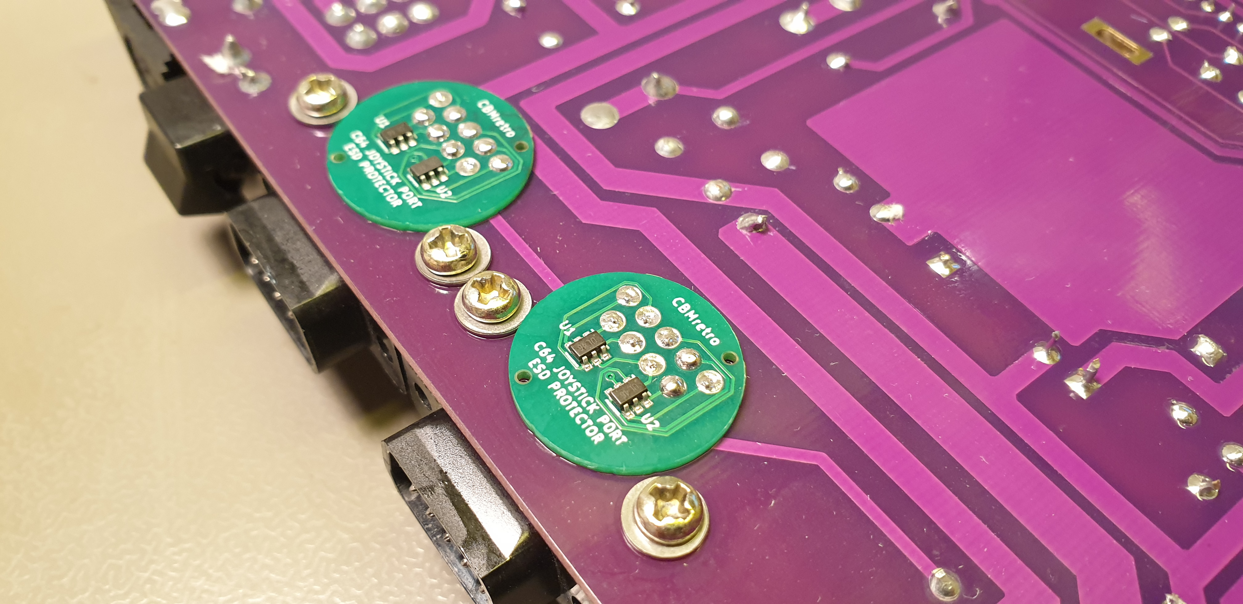
Luckily, you can get little boards with ESD protection ICs on them, for adding ESD protection to the joystick ports!
This is where stuff gets intersting, replacing these not only enables us to keep building more C64s, it also is what makes the MaxFake64 max fake.
The Complex Interface Adapters are two identical chips that handle stuff like keyboard, serial ports, joysticks, and timers.
The J-CIA seems to be 100% compatible..
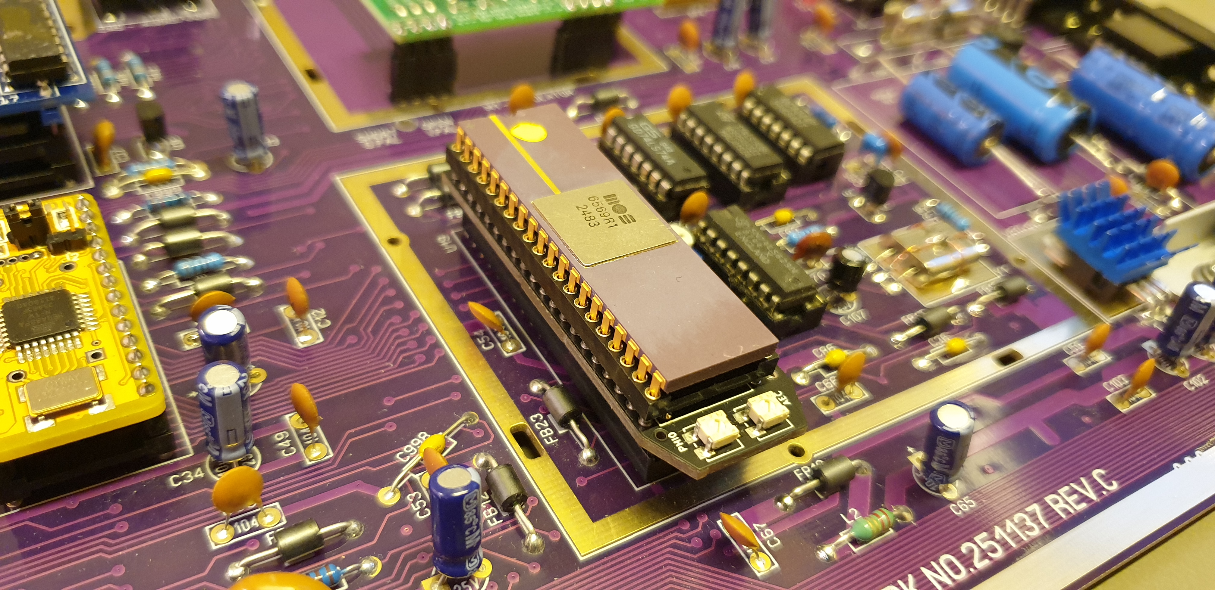
I started out with the stunningly beautfiul MOS6569R1, here it's in a lumafix board, just for fun (the lumafix works, but does add a slight softness that I didn't like, it also won't fit in a c64c case with the heatsink required by the VIC2
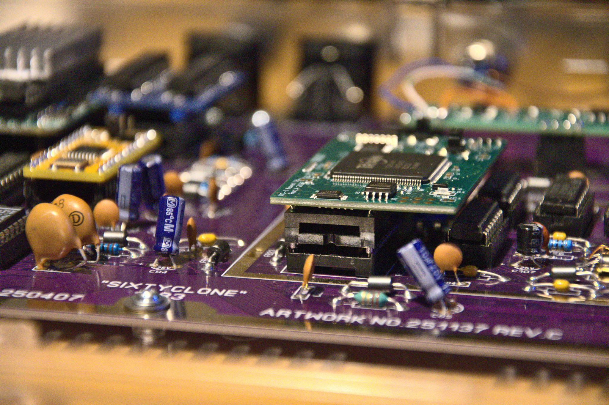
There is a replacement for the video chip, the Kawari. It is an FPGA replacement which can act either as PAL or NTSC, can bypass the C64 motherboard clock (I don't).
The 6510 CPU is actually a 6502 CPU with a few additional features, mainly, it can tri-state the address bus (so that the VIC can do stuff while halting the CPU) and it has a IO port at address 00/01.
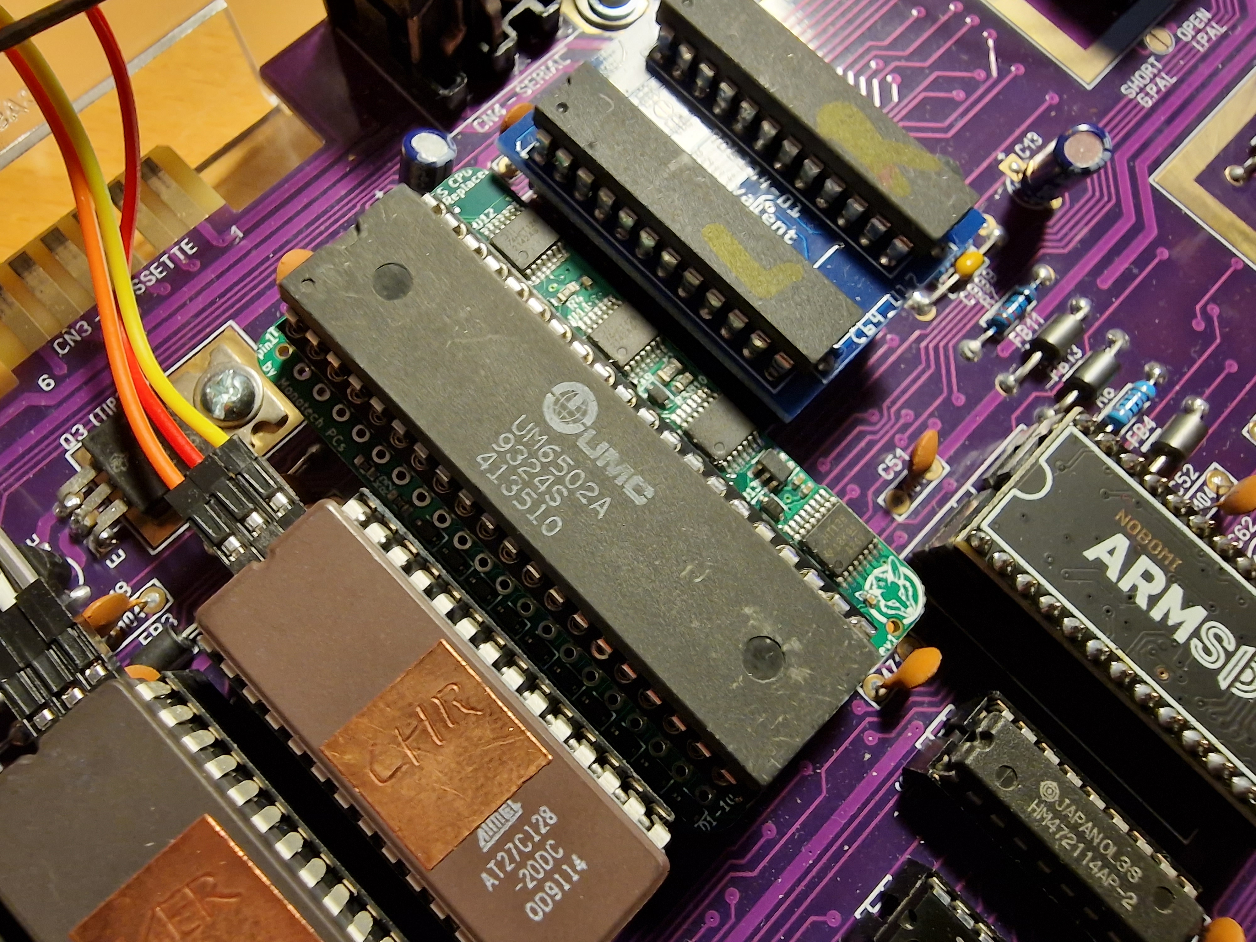
Monotech PCs (who also makes the very cool NUxT PC/AT motherboard) has made an adapter board that allows you to put any 6502 chip into your C64.
The PLA (Programmable Logic Array) is sort of interesting, it "just" glue logic, but it's role is very important, it is mainly responsible for mapping chips in at the right addresses. For instance, the kernal/basic/char roms can be mapped in or out of memory, and the PLA takes care of enabling/disabling chips as needed, depending on the current configuration.
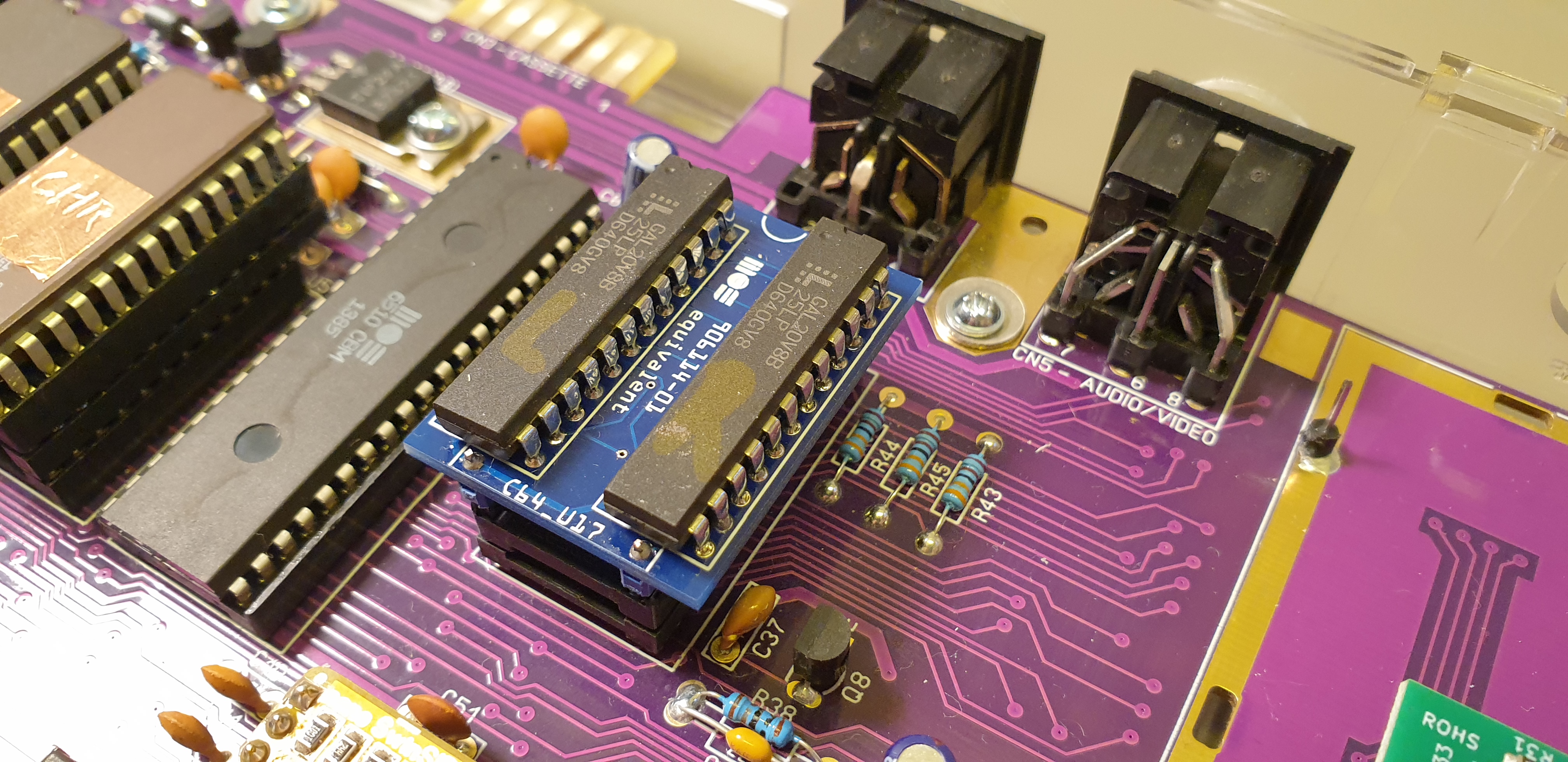
There's also some story about how commodore actually copied (badly) this chip, and it is mostly notorious for failing often. Luckily, it's been reverse-engineered long ago, and it's possible to use two smaller GAL chips to implement the same functionality, I absolutely love this because it's using period-correct parts and it's using two chips to do the job of one! such hack!
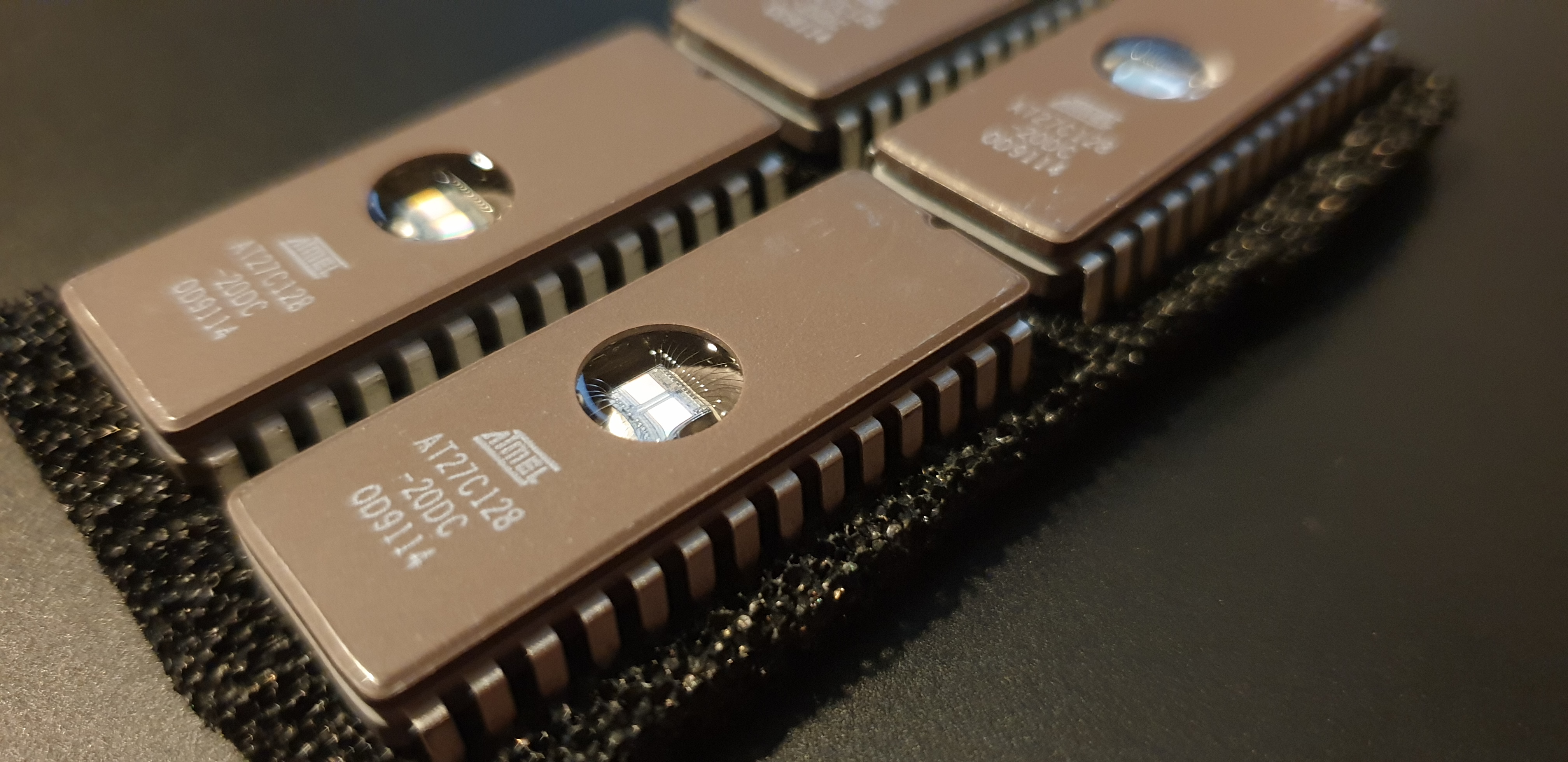
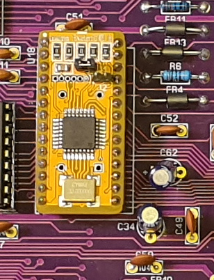
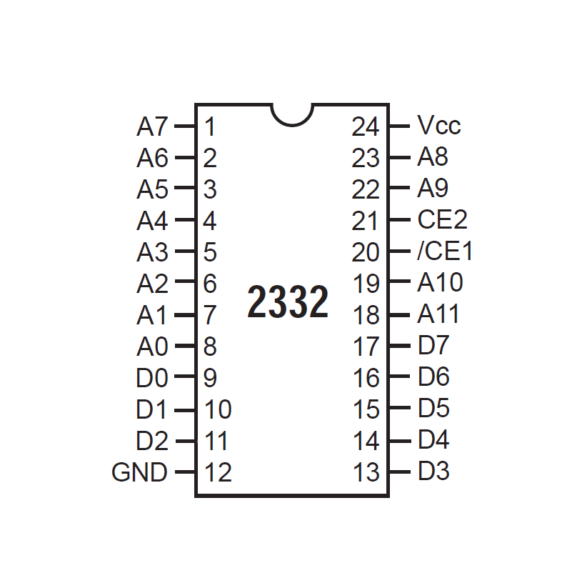
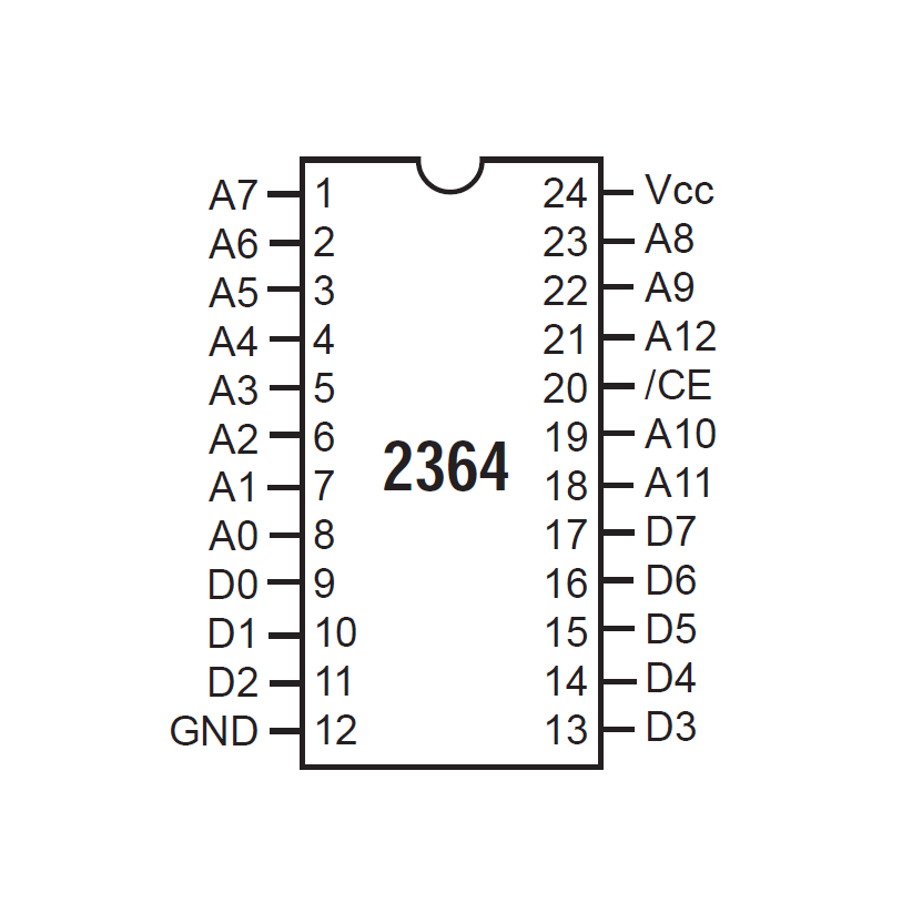
The C64 used MOS mask ROM chips for the firmware (basic, kernal, character bitmaps), those are basically hard-coded parallel memory chips. They can't be programmed, the bits are literally etched in the silicon as part of manufacturing.
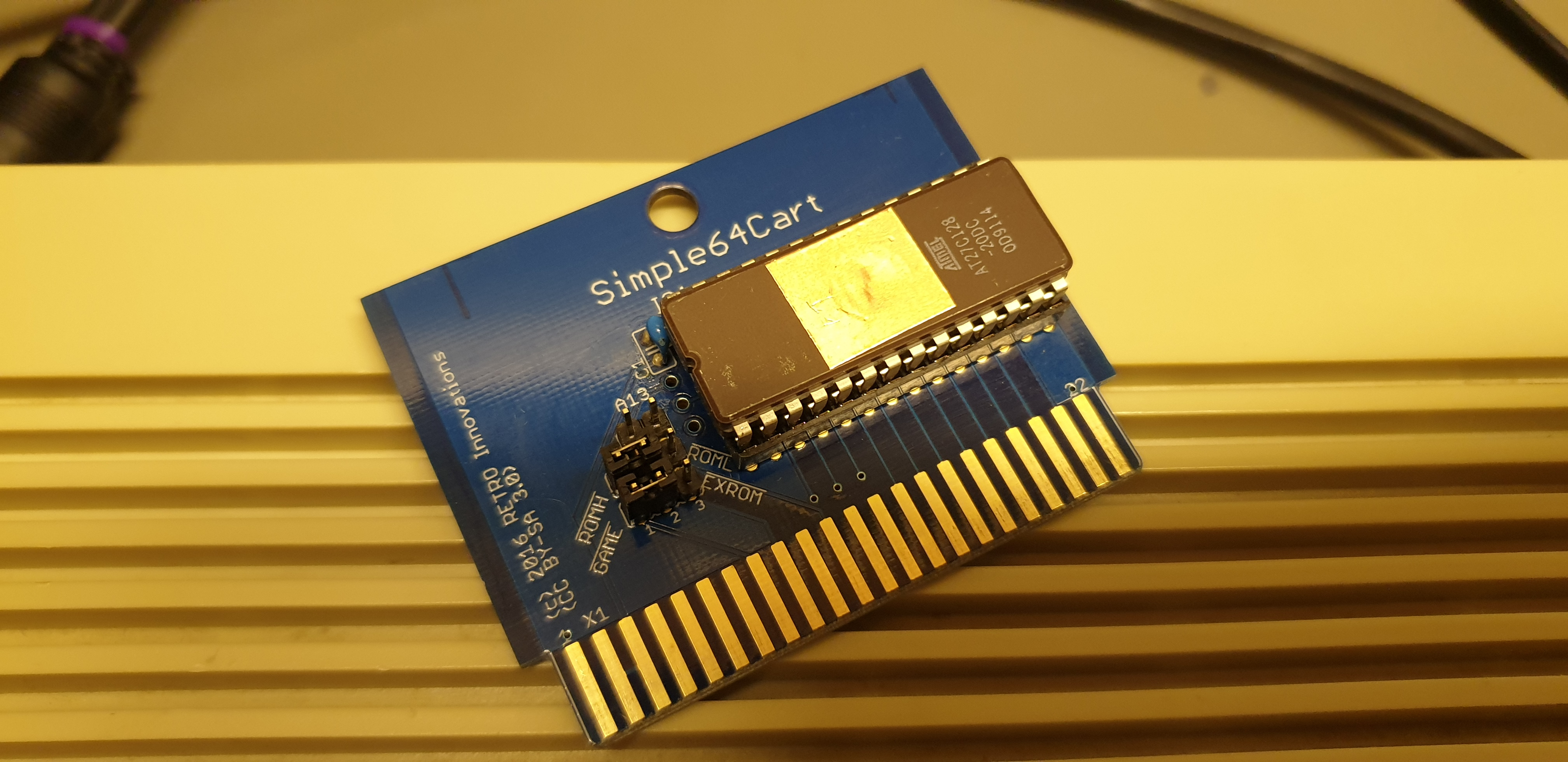
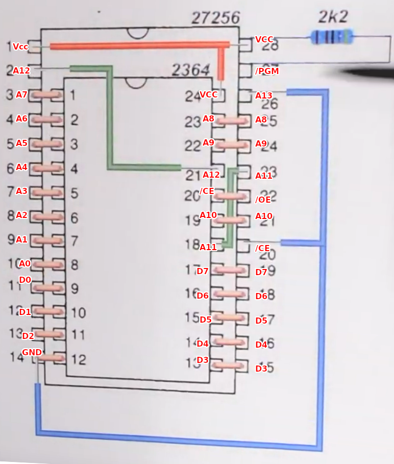
Luckily, they're fairly close to the pinout of standard EPROM chips of the same time, and it's easy to build an adapter to make them pin-compatible. Even cooler, it's very easy to build an adapter to also support higher-capaicty chips, allowing for alternate roms.
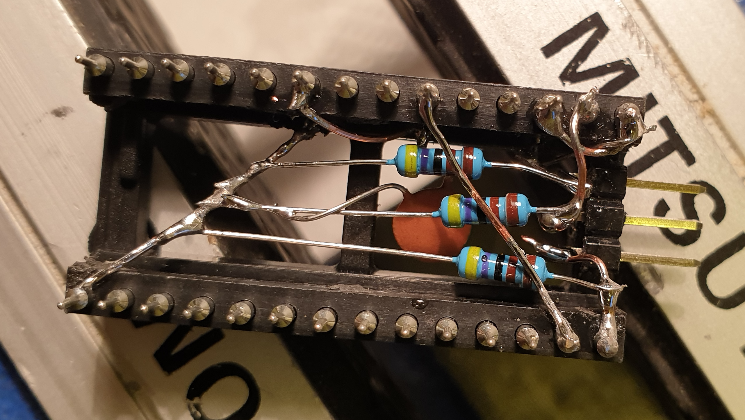
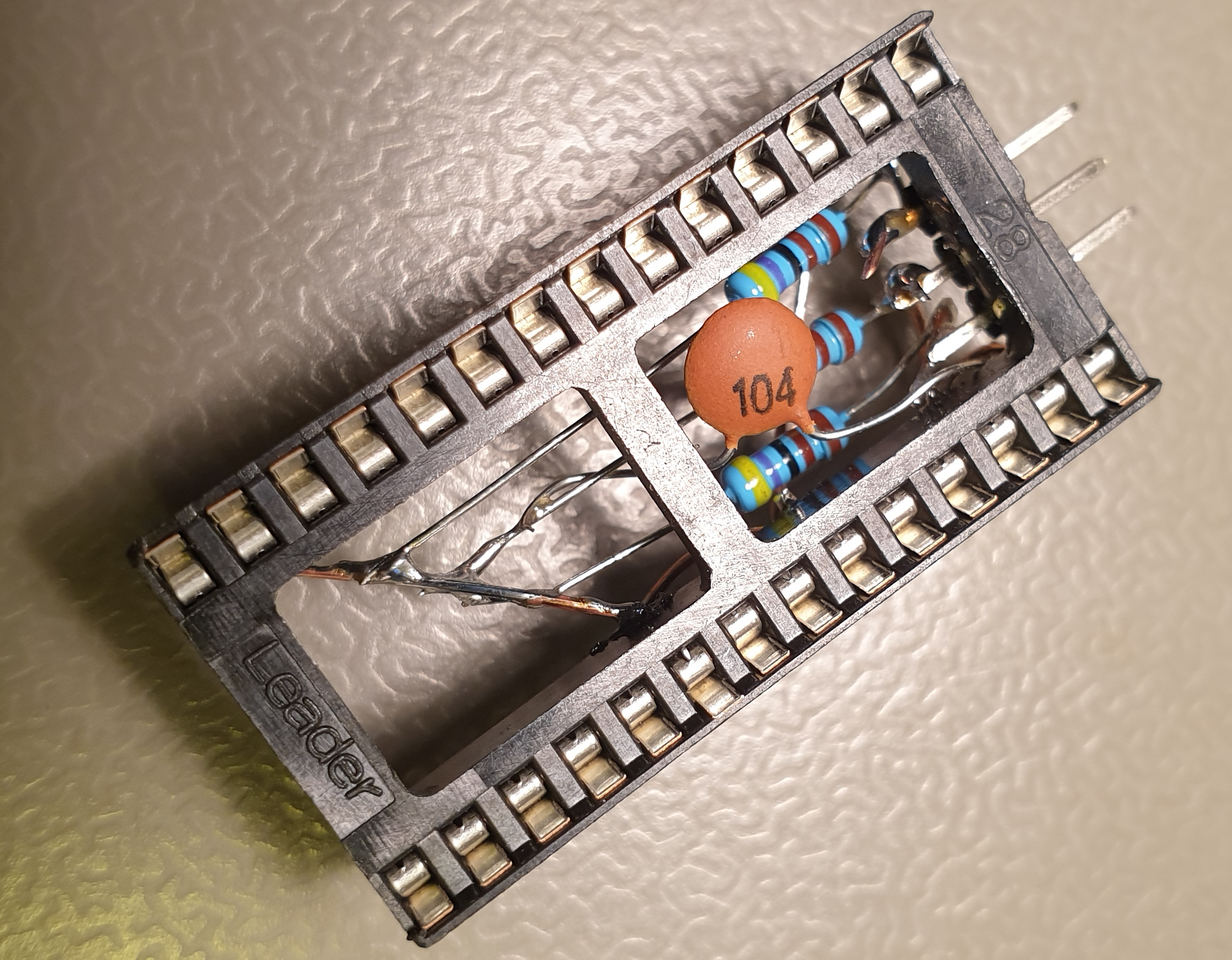
These adapters are made with two sockets, one regular dual-wiper on top, which have flat and bendable pins, so I can bend pins into the middle cavity where it can be routed to the second socket, a high-precision machined type which has the advantage that the pins have thin and thick part, where the thick part stays out in the open, so I can connect wires to that part without disturbing the socket "insertability". This combination allows me to route pins between two layouts in exactly the same footprint as the original socket.
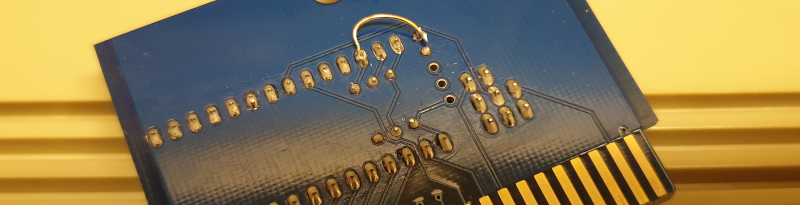
Because these chips are higher capacity than the mask ROMs used in the C64, I routed the extra address pins out to a pinheader, I also added some pulldown resistors, so if nothing was connected, the adapter would still work, and simply espose the first ROM image.
Additionally, because there was room, and because I'm not entirely sure if maybe the power usage could be higher for an EPROM than a maskrom, and because it never hurt, I added an additional decoupling cap right across the VCC and GND pins.
There's only one version of BASIC, so for this, I made a simple adapter, no extra options.
For the kernal, I have these roms in the chip
For the characters I have these
For the EPROMs I found beautiful ceramic UV-erasable ones from ATMEL that I'm using, it was fun using a programmer and burning my own ROM images, it felt like I was doing technical computer nerd stuff!

To select between the different ROMs, I could have gone with switches, but I didn't want to ruin the case or have wires dangling out of the back of the machine, so I used an arduino pro micro, it checks if the RESTORE button on the C64 keyboard has been held for a certain amount of time, then changes the color of the power LED to indicate which rom is selected, when the kernal rom has been selected, it saves this preference (to it's own itnernal EEPROM) and repeats the procedure for the character ROM. arduino pro micro firmware
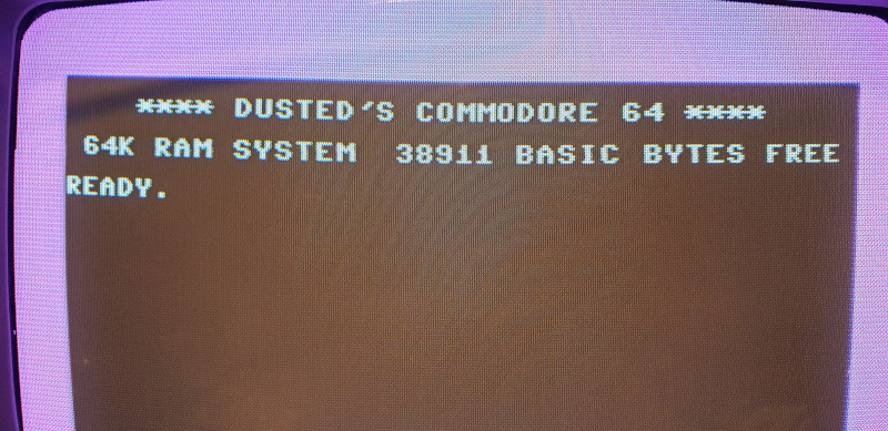
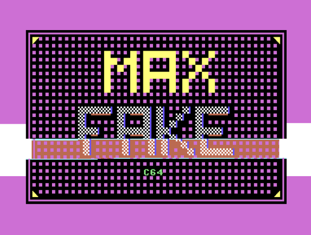
My custom rom, the most common version, but with my own colors and title.
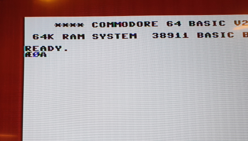
I modified the Danish rom to use the colors of our flag, so it's easy to see that it's not the US one, here it's also showing DK special characters using the DK character rom.
The famous Sound Interface Device chip, is a partly-digital, partly-analog chip and replacing this is sacrilege, but necessary for this project. The ARMsid is fairly nice sounding, but currently does not work with the 6502 adapter (I'm working on a fix). The nano SwinSID does not sound very good, but it is compatible, so I'm using that. (The 6581 is of course compatible too, but I'm trying NOT to use MOS chips, remember?)
The C64 uses a slightly uncomon "U" shaped DIN-8 for the A/V port. The more common DIN-5 connector can be used, but the common DIN-8 can't! This makes it annoying to build cables for it.
The luma and chroma pins for S-Video* are on the extra pins, so you can't build an S-Video cable with DIN-5.
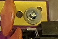
GX-12 "aviation" connectors look really cool and are easy to work with, mechanically strong and readily available, so I decided to put one in the hole where the RF-Out would have gone.

I soldered the composite, luma, chroma directly from the RF bypass board to the GX-12 connector, that board is installed in pinheaders so it can be removed easily.
This arrangement allows me to build any DIN-5 cable for audio that I want, and then any GX-12 cable for video, giving me maximum flexibility.
I used solid-strand ethernet cable wire for the video runs, these are rated for much higher frequency, they are very low impedance and extremely easy to solder, providing a better connection than the traces on the motherboard to the DIN-8.
* The C64 is a bit older than the S-Video standard, and it ouputs a slightly over-spec voltage on the chroma signal, but most TV's and the framemeister I'm using seem fine with it, if it's a problem, a 300 Ohm resistor can be placed on the cable to fix it.
This was a very cool project, and I am very happy about my machine, which I use very often, I am not so sad if something burns out, because I'm confidennt I can replace it, everything is in sockets, I have spare parts (at least original ones) of everything and everything is pretty new, or at least has not a lot of powered-on hours.
I feel confident that I'll be able to debug and fix whatever comes up in the future. But so far, I'm just enjoying having a very reliable machine.

Of course I have all the vintage gear as well, but for a daily driver, I think it's really neat to fake it as much as possible instead of burning out original c64's just to play through Giana Sisters for the Nth time.
The Pi1541 works really well, I put a largeish heatsink in there and overclocked it quite a bit before it was able to keep up with the FC3 and various demos turboloaders, but now it does and all is good.
It's never done.
Obviously the CIA chips need to go, they're the last MOS parts in the machine.
The FC3 will be recreated.
The keyboard must be a Mechboard64.
I won't tell you exactly, there are easier way of ridiculing oneself online, but it was an astonishingly expensive way of achieving C64 parity, of course, a lot of the reason for this was me not being picky about the suppliers, mouser is generally fair priced, but some of the other new-old-stock chips were bought at another electronics shop that was fairly expensive. The original salvaged parts that I used during initial build and test were also fairly pricy, the lovely cheramic VIC for instance was about $100.
Another way of saying it, adjusted for inflation, it cost _me_ more more to build than a brand-new C64 at introduction price in 82, maybe you can do it cheaper, I couldn't, or didn't.
A reflection on this though, is that it's still pretty amazing that a single individual can source and assemble all required parts of a mass-producted, super-cost-optimized machine without being multiple times more expensive than the original manufacturer.
We're in the last period of the golden age of electronics, as the world has moved to SMD and extremely-high-integration, the stores of cool stuff that we can play around with are being depleated, but let's make the most out of it while it lasts!
hvad.d64 Slideshow telling about this project, use F1 and F3 for prev/next
Unordered resources I've collected during this project
datasheets/AtmelEeprom27c512.pdf
datasheets/Eprom032k_datasheet_27C256.pdf
datasheets/c64c_service_manual.pdf
datasheets/MicroChip_27C128_11003L.pdf
datasheets/C64_Svideo_bypass_RF_replacement189512498.pdf
diagrams/2022-01-22-14-17-47.png
diagrams/2022-01-22-14-17-30.png
diagrams/2022-01-22-19-31-06.png
diagrams/diagrams/2022-01-23-01-15-17.png MaskROM to EPROM adapter, I wish I could find the youtube video where I grabbed the screenshot from, I will return to give credits when I find it!
Gallery of all pictures I took during the project, unordered and unedited