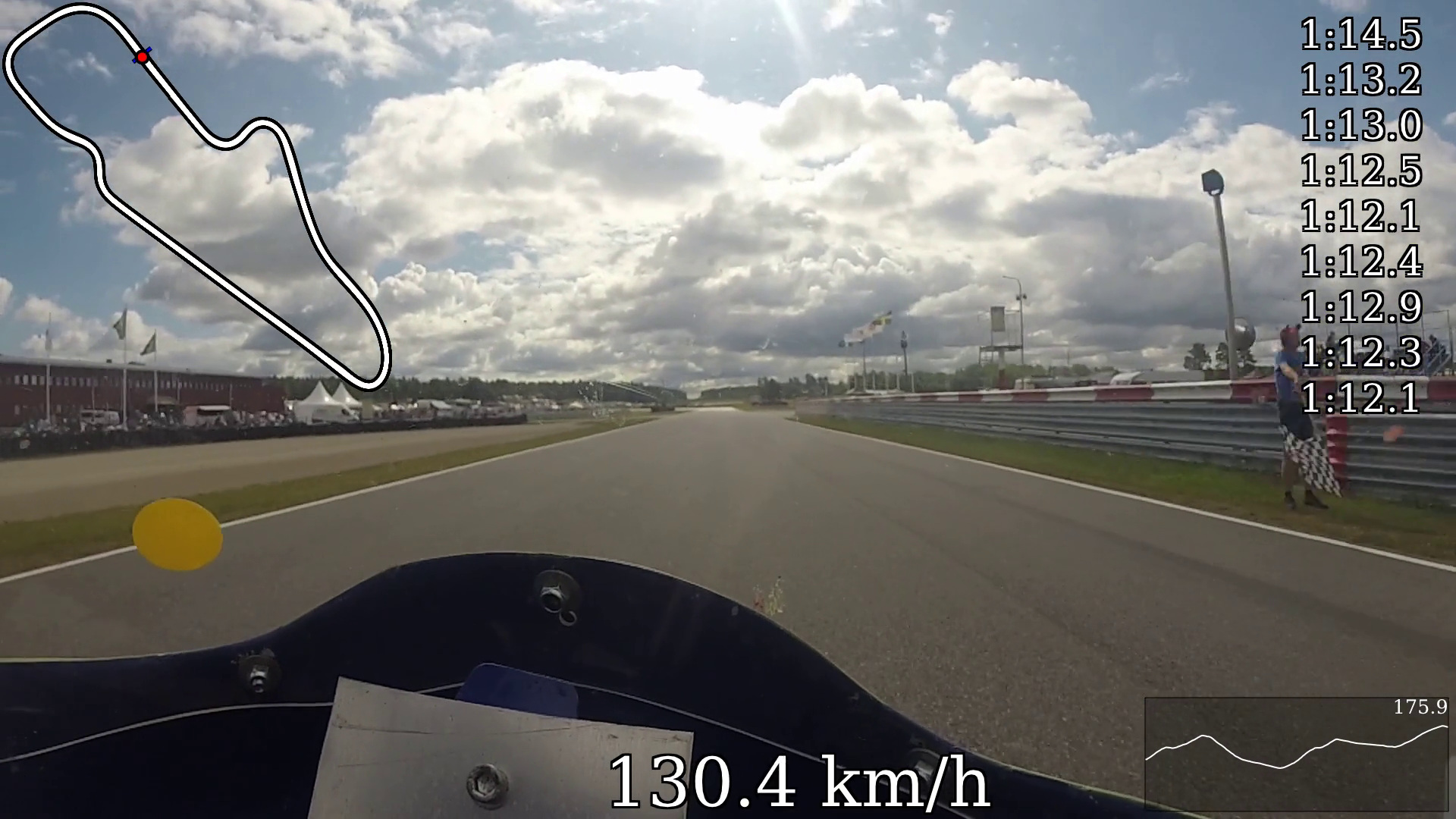
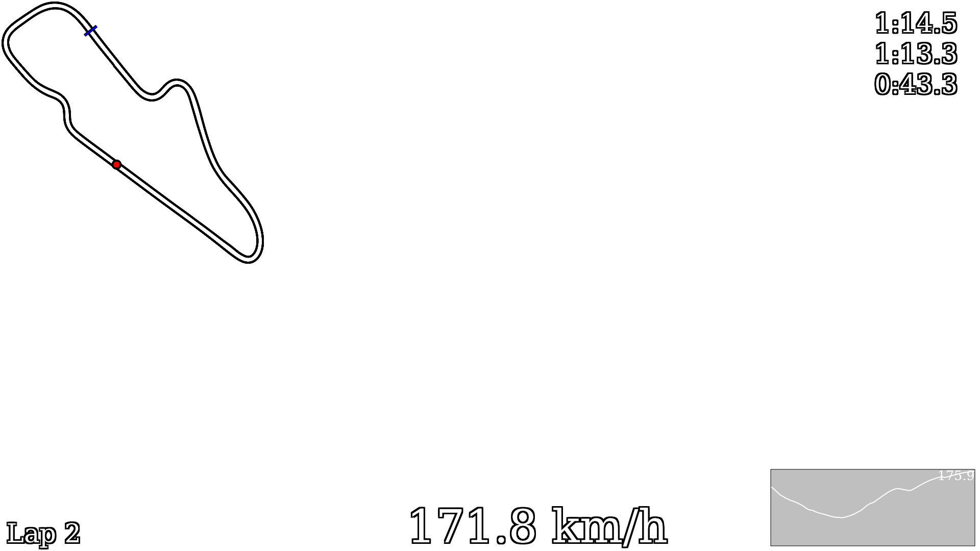
OpenSource solution for GPS video-overlay for Road-Racing. It is a high-speed (10 Hz) GPS tracker that records
position and speed to an SD card, along with software to convert those positions to a nice graphical overlay
to put on a video, for example from an action camera.
Motivation
I like building stuff. That's pretty much it. My father is a pretty good road race driver, and I though it'd be
cool if I could contribute to making his videos even more
interesting. By principle, I also like building things over buying them, even if they may prove inferior in some
ways, I will usually know how they work, thus I will be able to utilize and service them more readily.
Using it
Interface
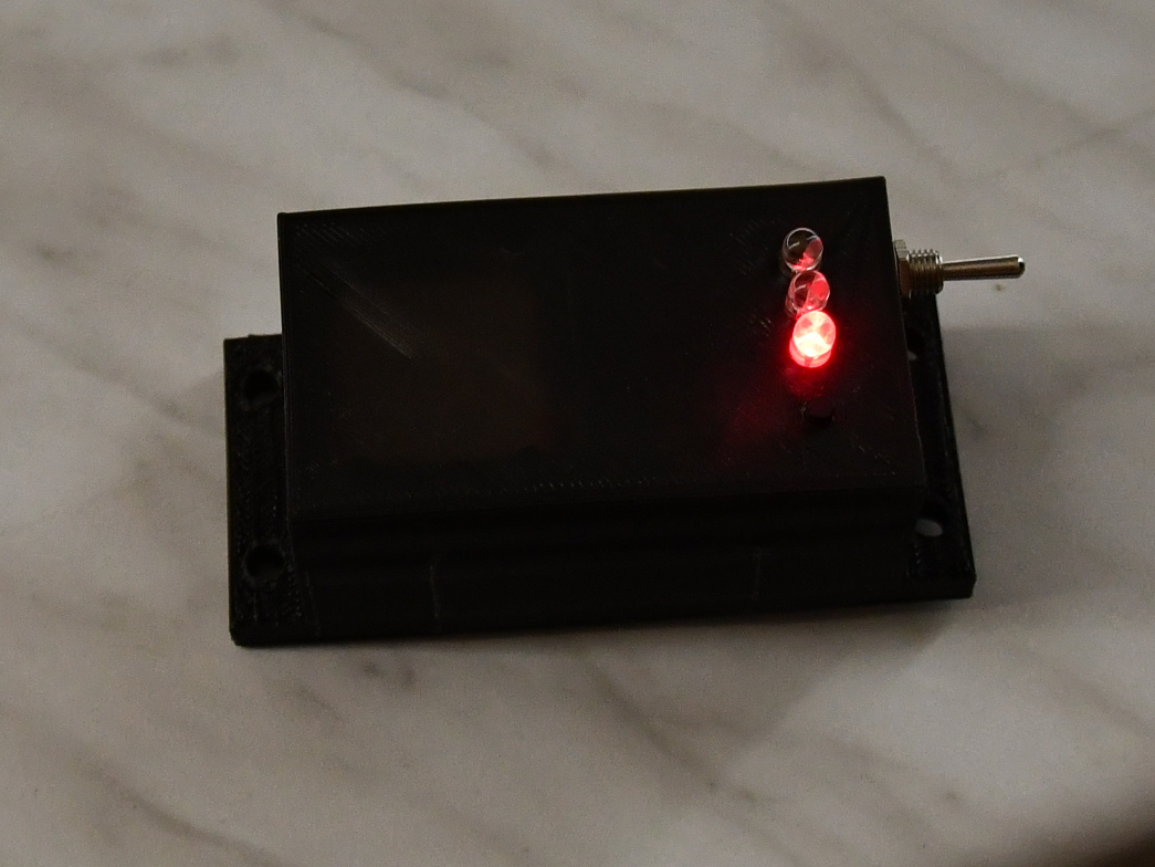
The toggle switch on the side turns the device on and off, one direction turns it on, the other direction turns it off.
The tact-switch on the front starts and stops the recording. Press once to begin recording, press again to end recording.
During recording, the file is auto-saved every 10 seconds, so if the device is turned off without first stopping the recording, a maximum of 10 seconds should be lost,
but it is still a good idea to stop the recording before powering off, to avoid risk of SD-Card corruption.
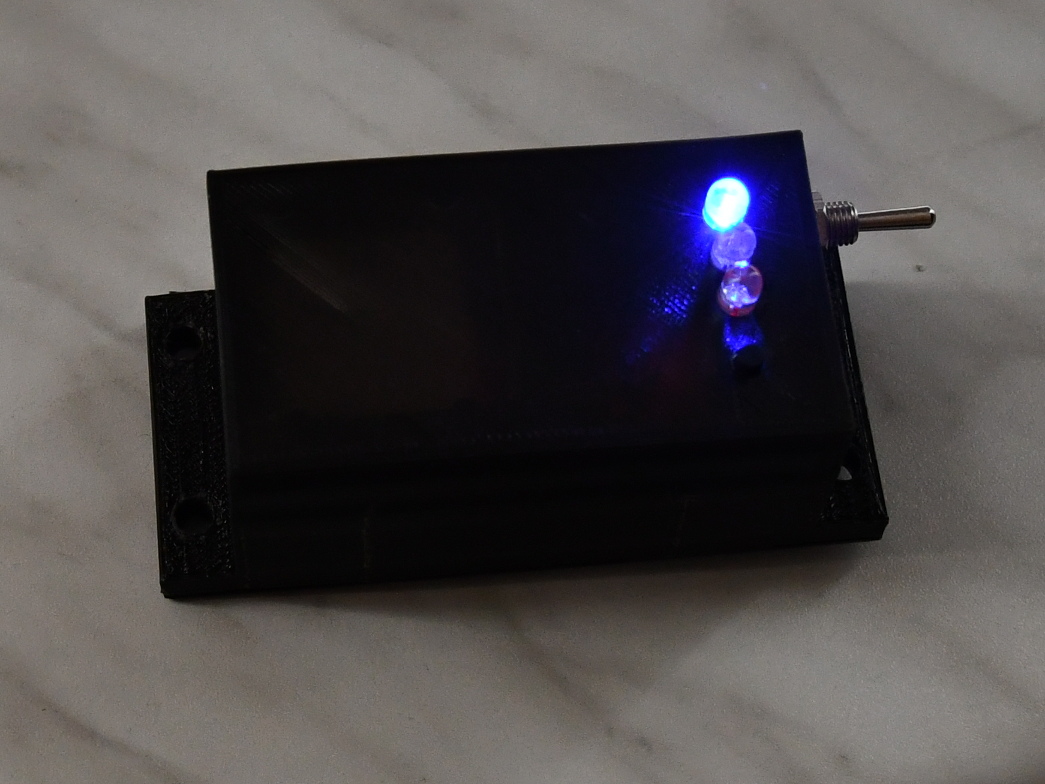
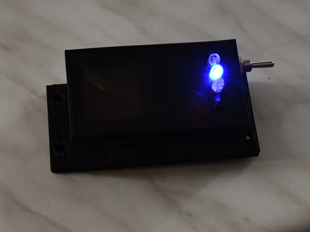
If the first led is blinking, there is a problem with the SD card.
LED1: Power is on, obtaining fix.
LED2: Power is on, got fix.
LED3: Power is on, recording.
Note: It is always okay to press record. If time does not allow waiting for a fix, just press record anyway. But, for the best results, turn on the device with a clear view of the sky 5-10 minutes before use.
Record a race
Turn on the GPS tracker well before it is to be used, so that it can get a good fix.
Turn on the camera
Start recording
Point camera at the tracker, so it is filming it
Press record on the tracker, thus filming the blinking LEDs on the tracker
Mount camera, go race, have fun, be safe
After race, stop tracker, stop camera
Create the video
Download GPS track (RMC file) from the SD card
Generate PNG images from the RMC file, by using "the framer" (play around with the parameters to geta good-looking
track)
Generate an alignment video (more on this)
Create a nice video clip from camera (I usually cut out beginning/end)
Use the alignment video to find the exact offset between GPS data/movement and video action
Use ffmpeg to generate the final results
After recording an RMC file, "the framer" software can emit a series of PNG image files, with transparent background,
for overlaying onto the video. Have a look at the README file in the framer directory for usage-instructions.
Download
This project is free software, it means you are free to use it, modify it, give it away and sell it. There are
no guarantee this will work, it might explode and kill your cat, you're on your own!
DC boost converter that takes LiIon voltage to 5v (no idea)
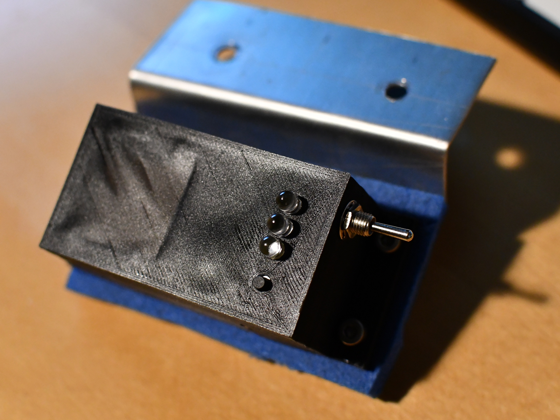
The Box
3 LEDs (5mm)
Tact switch (6x6x7 mm)
Momentary 1p2t toggle switch
Wires (I used some from an old ide133 cable)
Notes
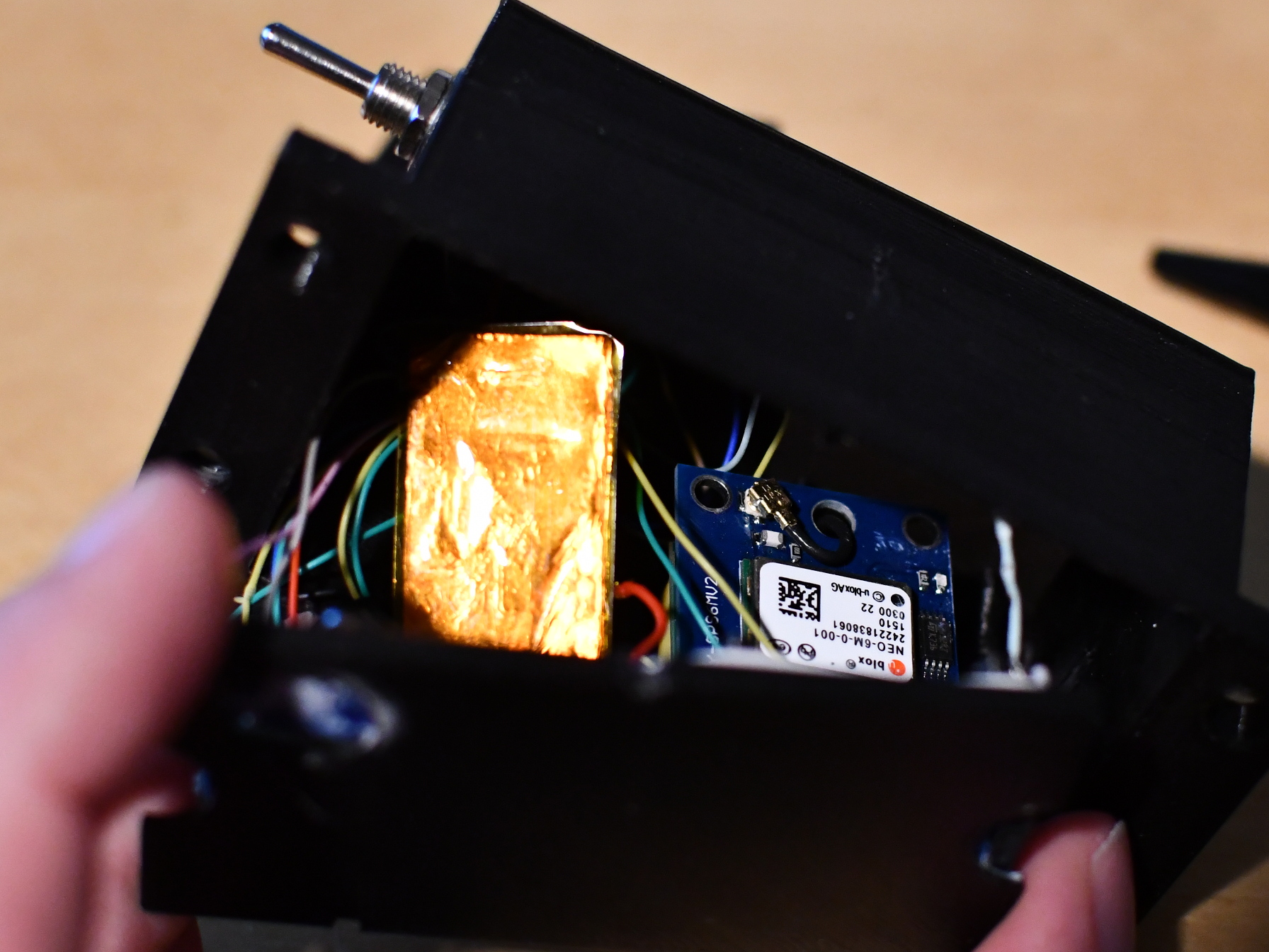
Now, the only thing that will be consistently sourcable is likely the Arduino Pro Micro (clones).. The GPS modules
are rather varied, the one I got has an antenna block, and no connector for an external antenna. This makes it
difficult to actually buy the parts and know that they will fit inside the 3D printed case that I made.. On that
note, my case is not that good, and I actually ended up messing it up a bit, so, yah, make something better ;)
As for the SD card reader, the one I got is very slim, but I see those are going out of style in favor for ones
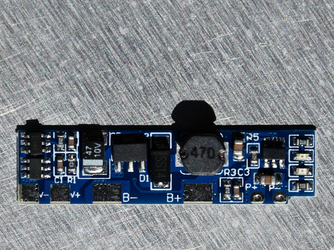
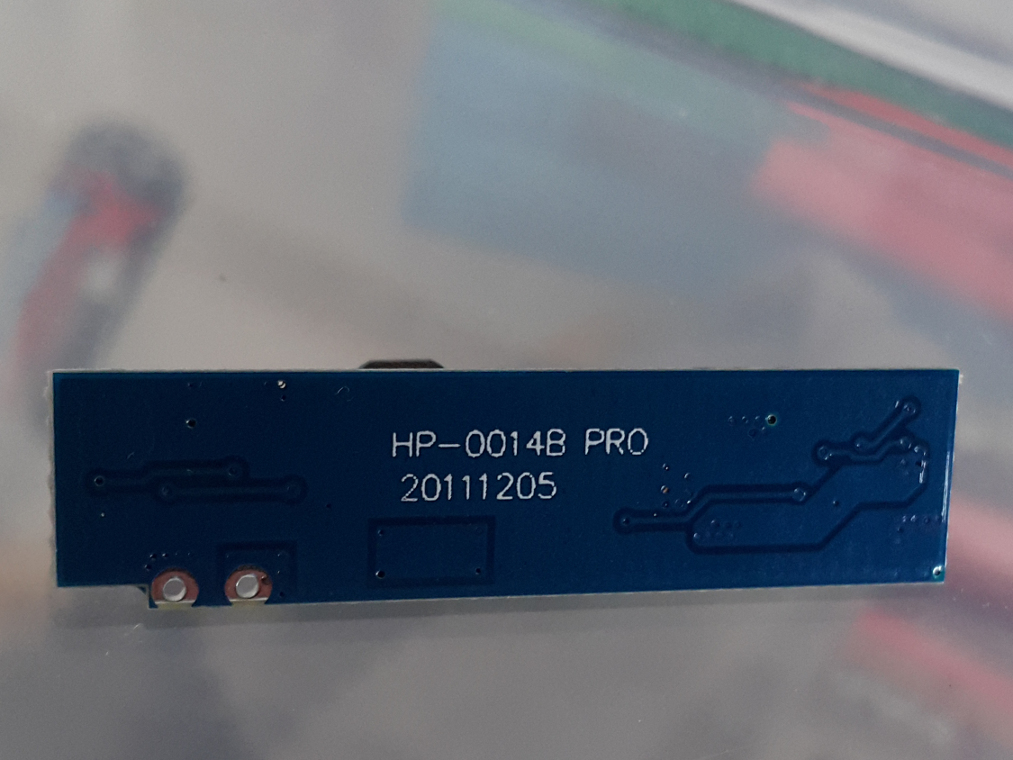
with mounting holes, which I figure is generally preferrable. The power supply board I've got is quite a mystery,
I've used those before, but I forgot how I found it.. It's a little dc-dc converter that steps up the battery
voltage to 5 volt. It has a passhtrough for charging, and undercharge protetion. The power-supply also has on/off
state, When shorting bat- to p- it turns on, and bat+ to p- turns it off.
I chose to remain in the comfortable 5 volt country where I've lived my whole life, even though I could likely
have gotten much better battery performance from going pure 3v3. I might have considered that if I'd got a 3v3
arduino and a power supply.. But I didn't, I've just ordered some now, I guess this is the time to start making
the switch..
Schematic
I didn't draw one, just connected what fit.. Kind of wrote the firmware at the same time, and didn't clean up,
which is evident from how pins are assigned, anyway, here's how it was done:
    preCAD v 0.1 (just kidding)

     ^ = +5v, on the psu
     v =  0v, on the psu

     +-----+
     | GPS |
     |  +5 |--^
     | gnd |--v
     |  rx |---- tx on arduino
     |  tx |---- rx on arduino
     +-----+

     +------+
     |  SD  |
     |   +5 |--^
     |  gnd |--v
     | miso |---- 14 on arduino
     | mosi |---- 16 on arduino
     |  sck |---- 15 on arduino
     |   cs |----  9 on arduino
     +------+

     +-------+
     |arduino|
     |   vcc |--^
     |   gnd |--v
     |     4 |->--- LED3 cathode, "recording" indicator
     |     5 |---- green wire, for uart mode (tx)
     |     6 |---- LED1 cathode, "waiting for fix" indicator
     |     7 |---- LED2 cathode, "got fix" indicator
     |     8 |---- yello wire, for uart mode (rx)
     +-------+

     +-----+
     | PSU |
     |  b+ |---- To the battery + terminal
     |  b- |---- To the battery - terminal
     |  p- |---- To toggle switch pole
     |   + |--^
     |   - |--v
     +-----+

     +-----------+
     | Toggle sw |
     | Terminal1 |---- To battery+
     | Terminal2 |---- To battery-
     +-----------+

     +---------+
     | Tact sw |
     |  Side 1 |--^
     |  Side 2 |------+------------- 3 on arduino
     +---------+      | +-----+
                      +-| 10k |--v
                        +-----+

     Repeat x3:
     +-----+
     | LED |     +------+
     |Anode|-----| 150r |--^
     +-----+     +------+
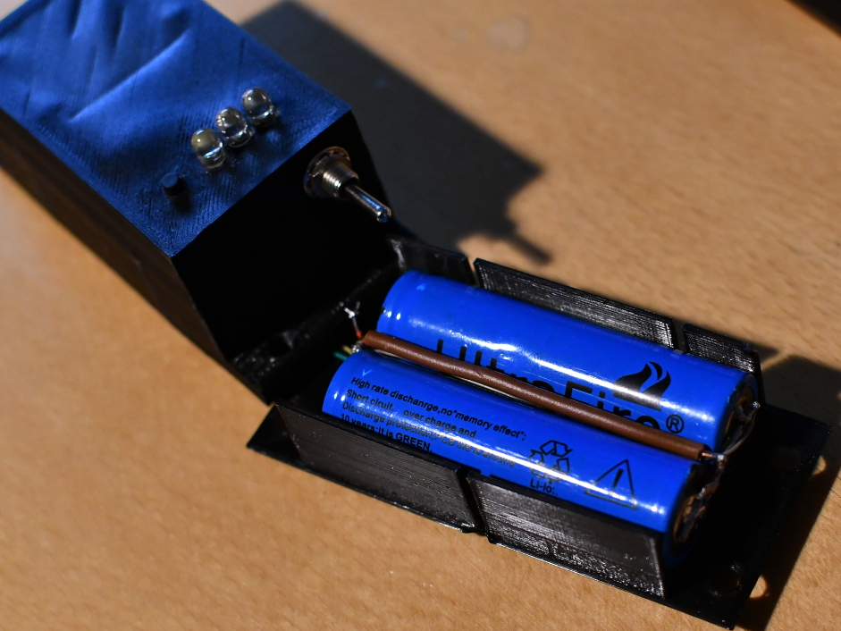
And that's all for the schematics, the two 18650 cells are wired in parallel. A black wire goes from the PSU 0v
and out of the case, to provide ground for UART operation. A gray wire goes from the battery-, a red from battery+,
and out the case, to provide a means of charging the battery. The yellow and green wires goes out of the case
as well, for the same, obvious reasons.
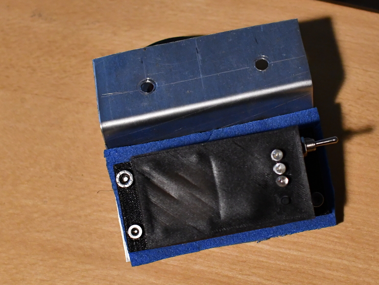
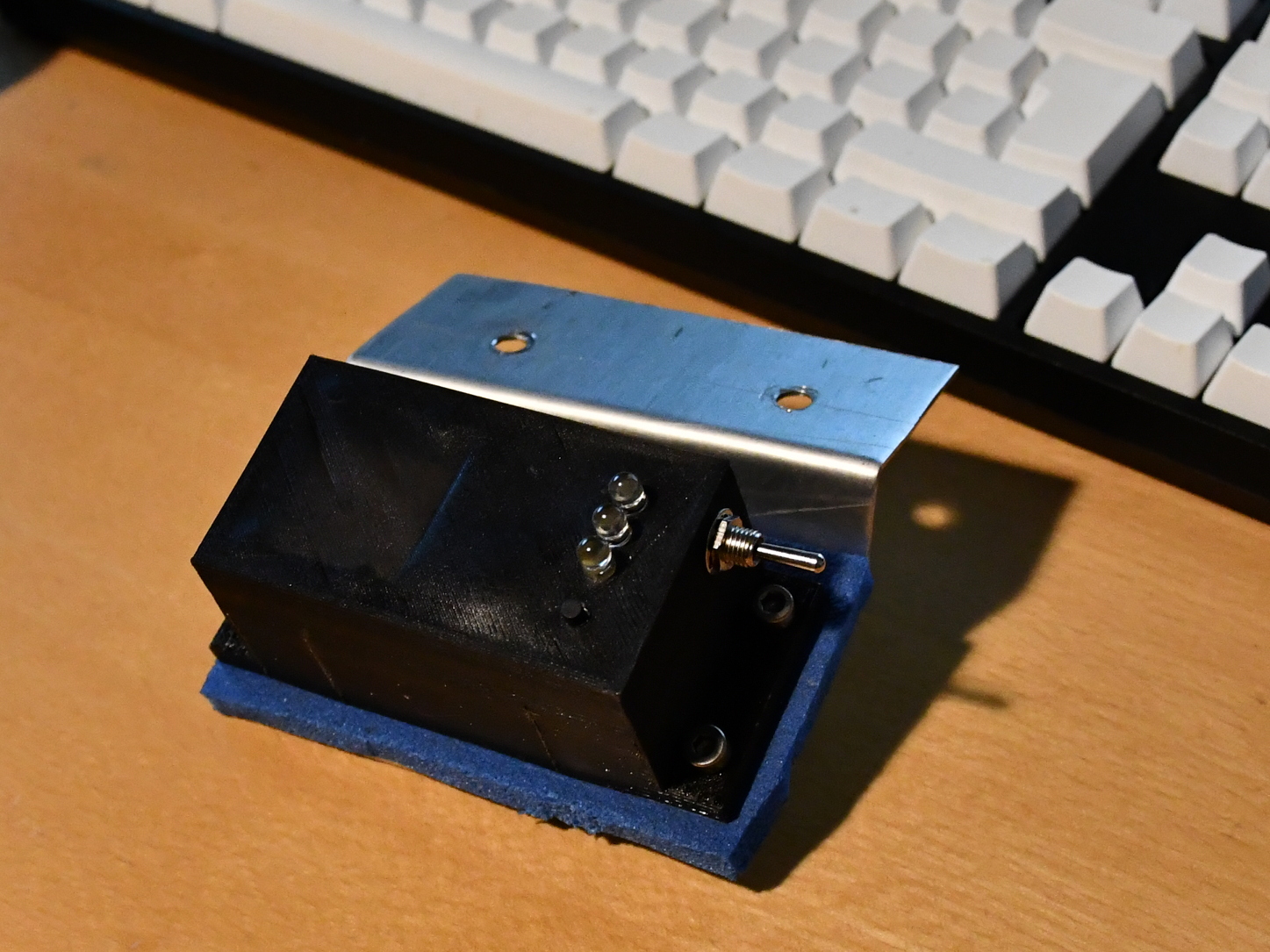
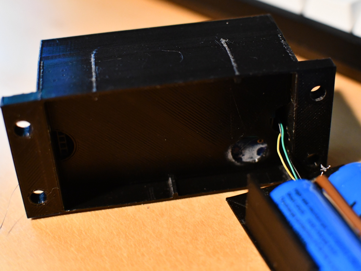
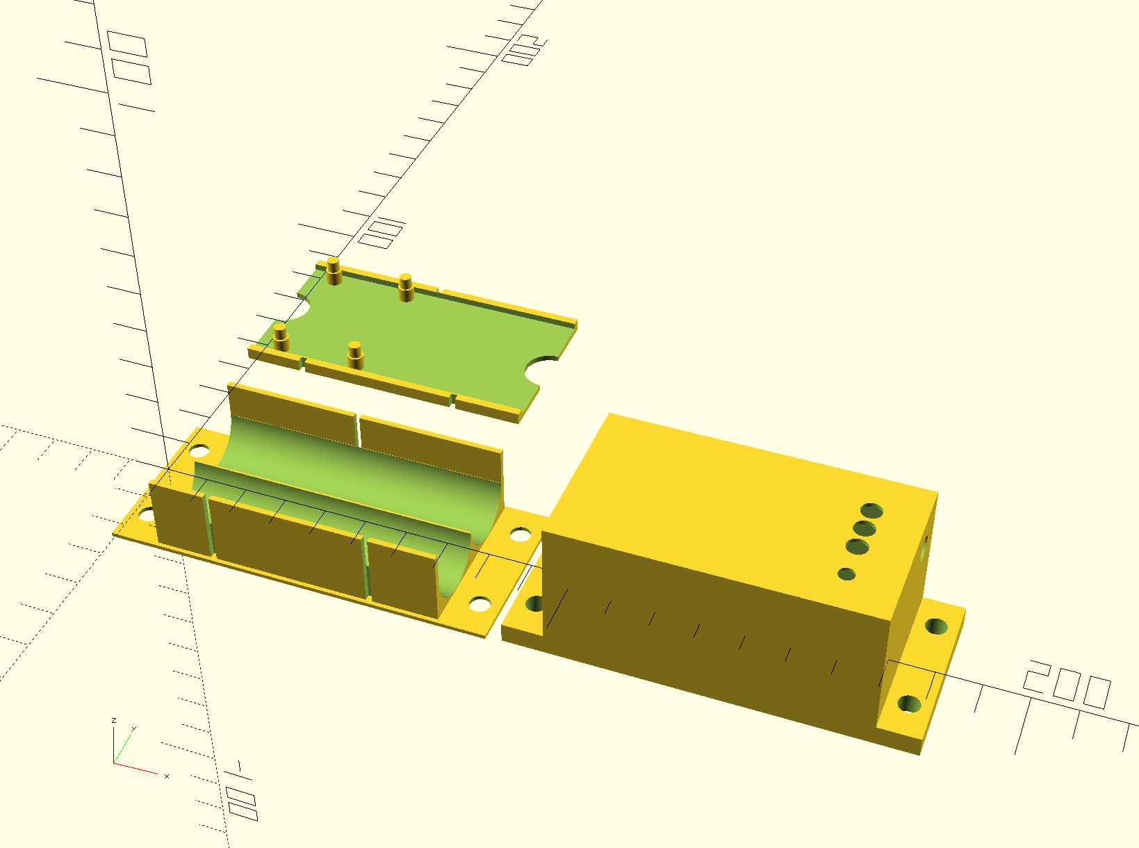
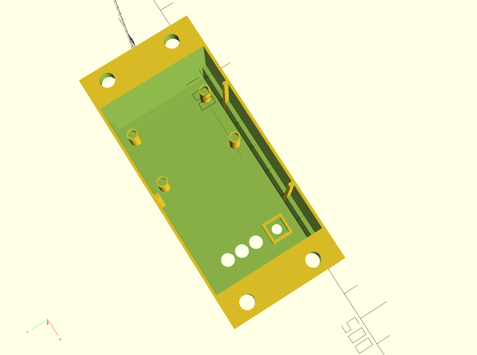
The Box
Aside from referencing a track by orbital,
the case ended up being both over- and under-engineered at the same time.. Some of the dimensions were a tad
too much for my 3D printer, and other dimensions were a tad too optimistic when taking into account my limited
skills within the field of handicraft. Two lessons were learned. First, a top-lid would have been much easier
to work with than sliding everything Up from the back of the case (wires were crushed and such), and I have no
hope of taking it apart to do any sort of repairs. Second lesson: The fit was too tight, especially the guide-rails
I put in to make it easier to get it together, they introduce just enough variance that it does not fit beautifully
together. Anyhow, the scad file is at the git project where I keep the openscad stuff. You need to do 3 render+export
steps, because I'm lazy. top(); middle(); bottom();
The firmware
The firmware is a trivial Arduino sketch. It sets up the GPS module for 10hz nmea RMC messages, and reads the button to start/stop recording. It opens a new file, following the pattern "%02i.RMC" and writes samples to it.
Every 10 (or so) sample, it will close the file and open it again, to avoid losing all data if power is lost before the recording is lost. For no particular reason, I decided that the $GPRMC, prefix was not needed, so
it is stripped before being written to file. The \r\n is replaced by a single pipe, the | character, as I found it easier to work with while debugging in putty.
If the record button is pressed while power is turned on, the device boots into file-transfer mode, allowing listing, downloading and deleting the files stored on the SD card. Three wires (GND, RX, TX) are exposed
to allow connecting to the device via serial, 5v, 28800 baud, to avoid having to take the device apart to download files. This serial connection is driven by the Arduino software-serial library, as the hardware serial port is used by the
GPS module, and the usb port is difficult to reach. A hole could have been made in the case to allow this, but due to lack of room, I found it easier to simply route the wires.
Lessons learned
The most important thing: Don't try to make things smaller than you're capable of! This ended up causing a bit
of grief, especially, the mechanical connection between the batteries and the PSU was too optimistic. I had soldered
two pins directly to the battery, and glued a pinheader in place, resulting in a very rigid structure, this simply
broke apart due to vibration. The solution is to string wire, which can take the vibration a bit better. I'm
not looking for professional-grade enginerring here, I'm seeking a compromise between stability and effort.
Do something to mark the record button. When I first gave this to the driver, he was not able to see the record button, as it is black, on black... I put a small dot white paint on the button to fix that problem.