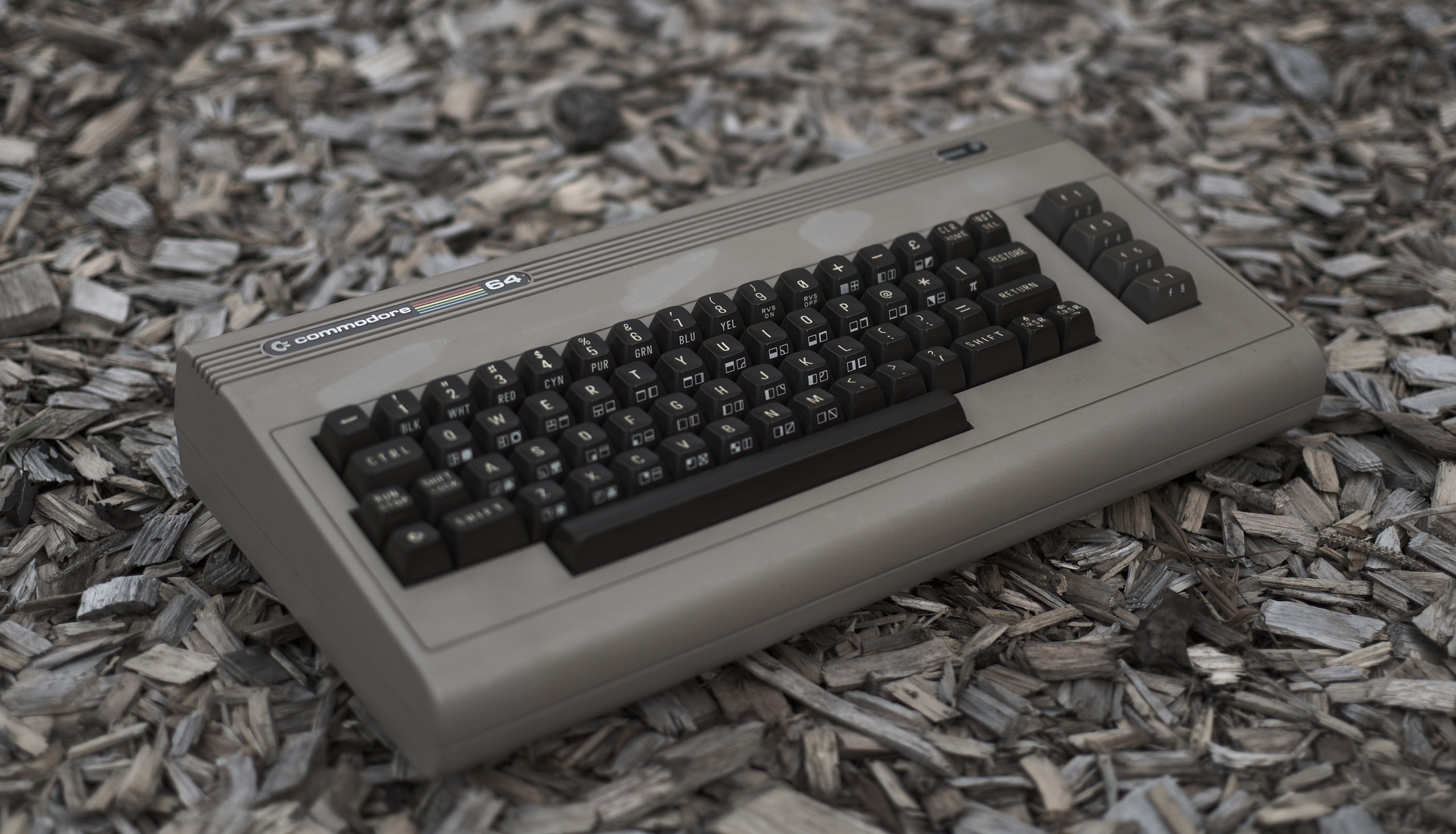
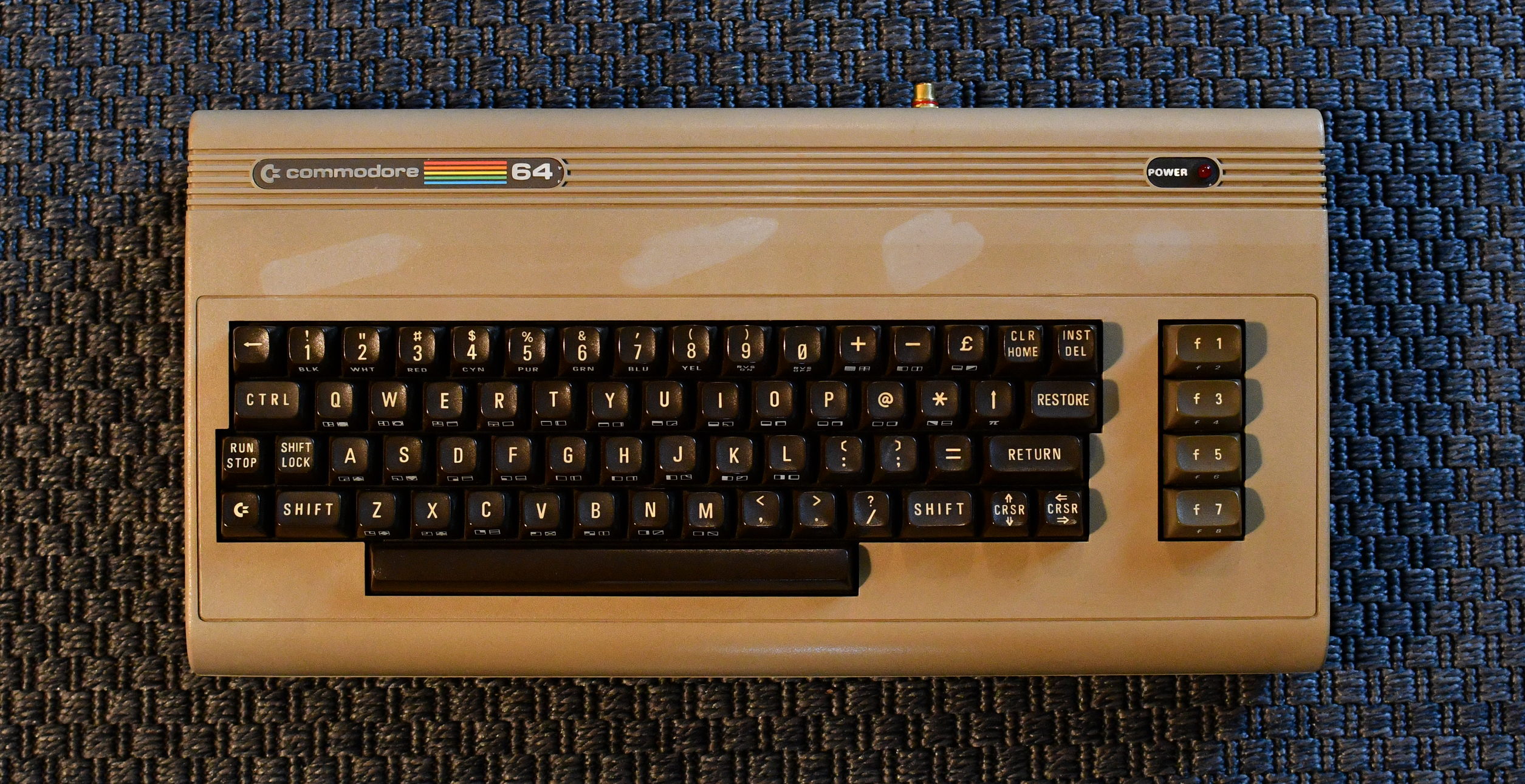
I've had a lot of fun with my IDE-64 setup in the past. However, the Ultimate64 intrigued me, as
it is an FPGA implementation of a C64, so, not an emulator, but actual new, compatible hardware!
I had to get one! I won't go through all the features here, you better visit the official site
https://ultimate64.com/ to read all about it! It's also still in development, so the more I write about it, the more it'll be wrong later on.. Suffice to say, that so far, it's ran everything I've thrown at it perfectly!
It was raining today ^_^ Hey, it's my website! I don't have to stick to the topic!
Storytime
It was long ago, that I came across a broken C64 with an ugly case, and decided, at that time, that I wanted to put a mini-itx computer inside it and use that for my C64 needs. However, the itx motherboard i got was quite bad, and I never got far with that project. I did spend the ~40 eur on a KeyRah which works perfectly, but won't be used.. I'll give this to somone who's going to use it (for example with a Rapberry pi) eventually..
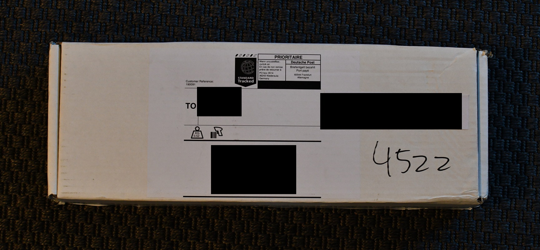
Packaging was adequate, as in, it survived, and inside the box, the board was wrapped in bubble-wrap which was secured to a piece of cardboard, in such a fashion that rather large bends to the outer box wouldn't reach the board itself.
there is room for the box to deform somwhat on all axis without the board being stressed. This is good packaging for a project of this scale (I used to ship finalkeys in nothing but an envelope and a a round of bubble-wrap).
In the box were two items: * Board * Powersupply. That's it, no manual, insert or anything else. That's quite okay, as there is a good description on getting started on the website.
The PSU seems to be of a fair enough quality, 12 volts at 2 amps means the Ultimate64 can consume about 24 watts, I've not measused actual usage, but the PSU has only gotten lukewarm, it is a switching powersupply, which explains the modest size along with the fair power rating and cool temperature. The PSU I got is fitted with a green LED which lights up when the supply is powered on, and a normal barrel plug.
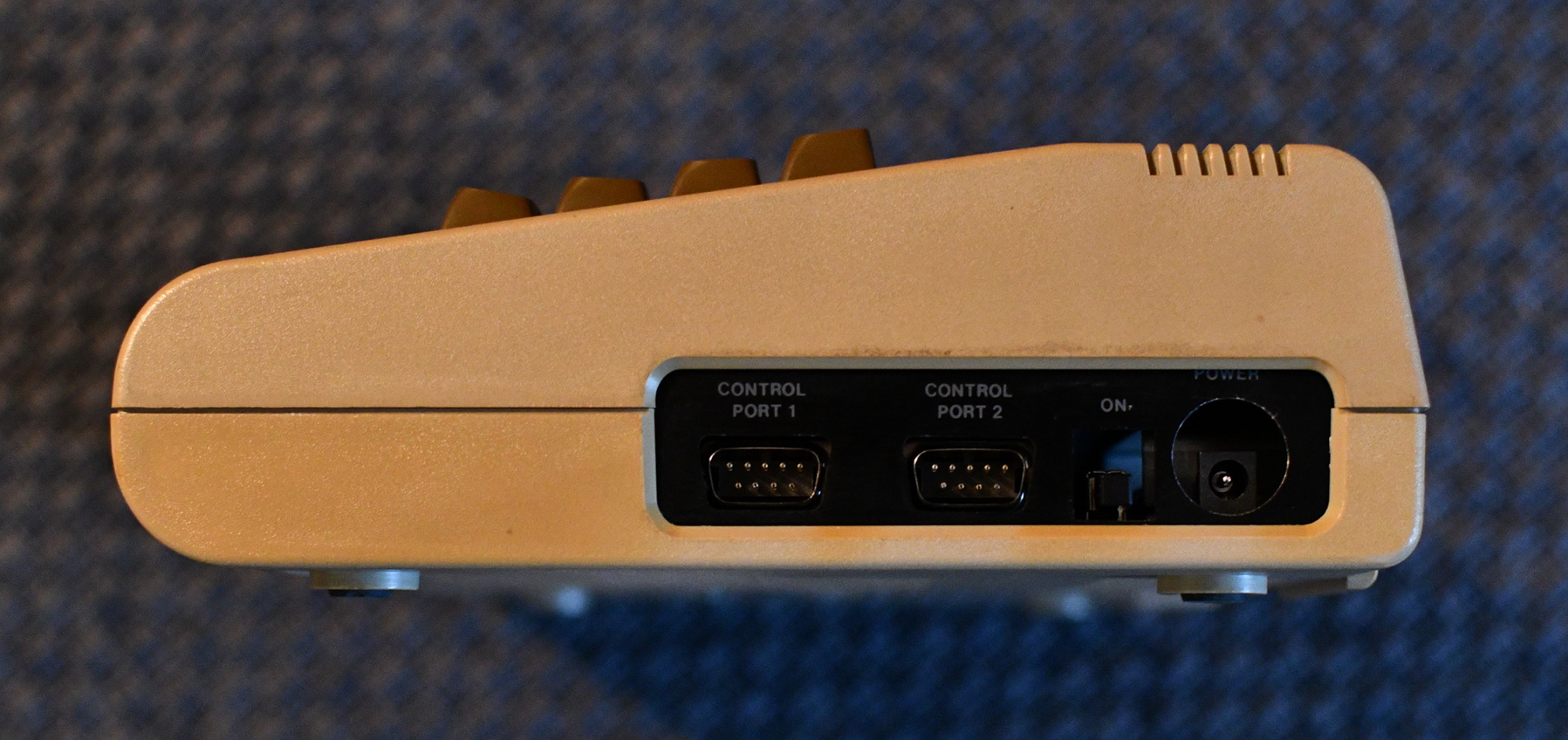
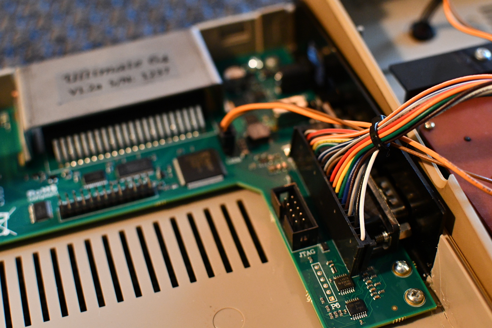
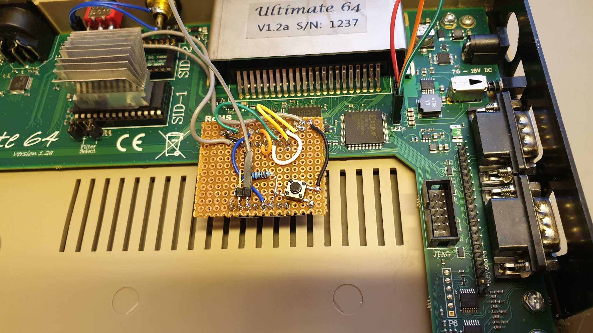
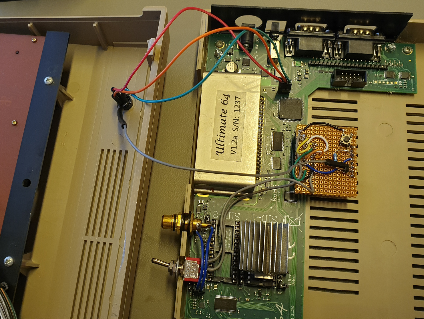
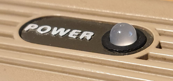
The board installed: The metal shield screws onto the board, as with the original C64 board. Joystick ports are where you expect them, the power button too, though this is a momentary switch, serving multiple purposes (power on/off, ultimate64-menu, reset, freeze). It feels sturdy, but requires a bit of force to press. This is probably no cause for concern, but I anticipate this button seeing a lot of use, and would prefer to mainly use another button fixed to the case, I'll add one later, but there is no header for that (as far as I found) so I'll have to solder on my brand new toy in order to do that.
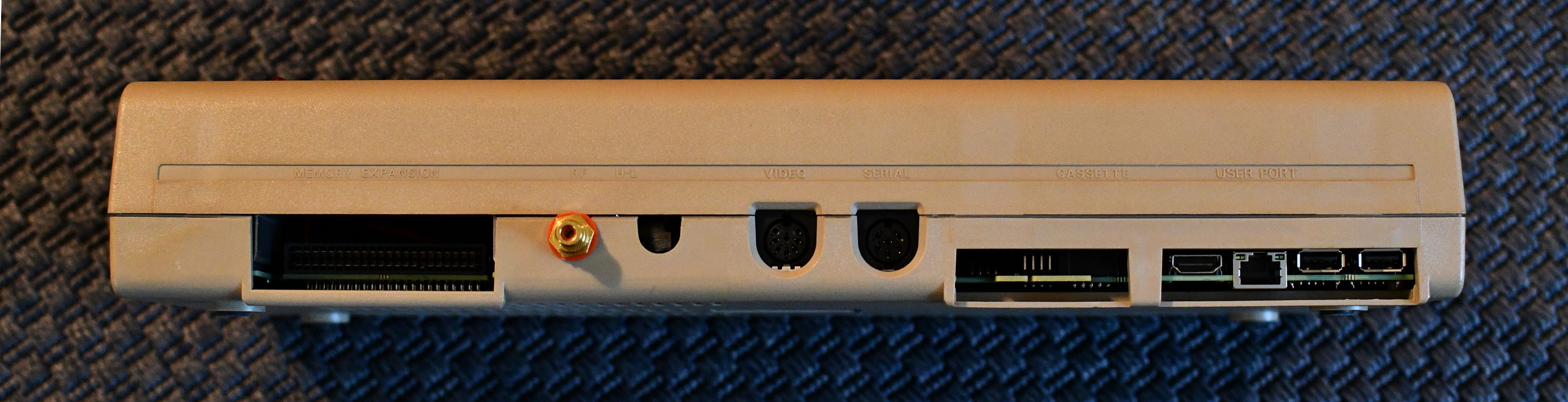
Backside, the userport is missing! But that's kind of okay, there IS an internal header for the userport, so if you really want to, you can attach some cable to that (ribbon cable with a header connector), I might do that at some point to play around with hardware dev, I've never done anything like that on a C64 before, so why not? :)
The USB, Ethernet and HDMI ports make nice use of the space! Note that there is an additional internal USB port, nice touch!
The board provides the well-known memory-expansion (cartridges), video, serial and cassette connections, these connections behave as expected! So yes!
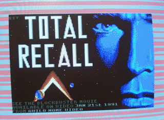
You can load games from tape and diskette on this 2019 piece of hardware!
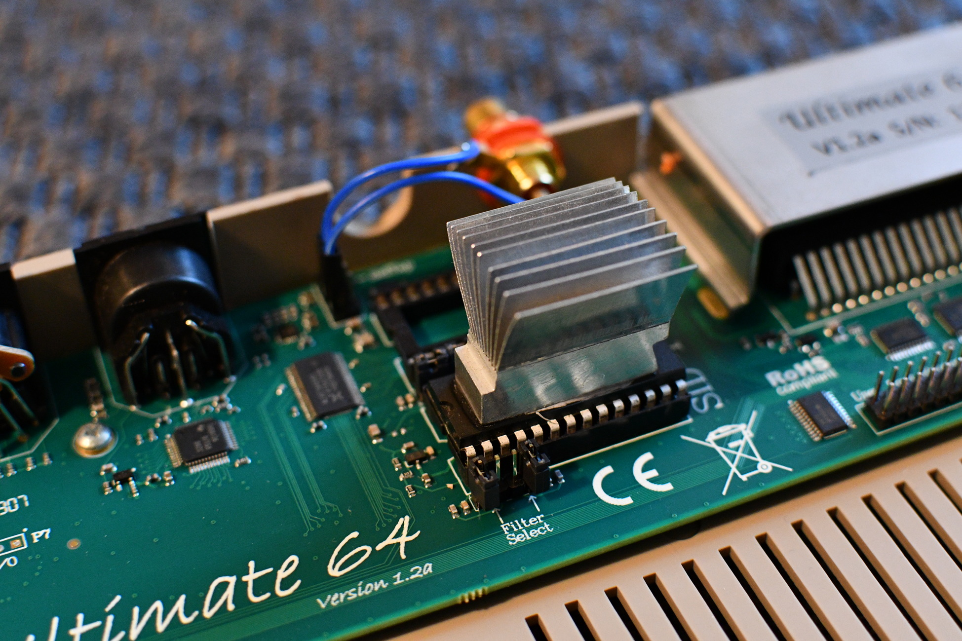
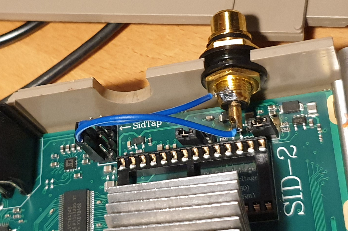
Note the red plug.. That's NOT on the board, it's analog audio directly from a real SID chip, more on this later.
Top view, nothing much going on.. The power LED is the original, in its current configuration, it lights up when there's power, and turns off when the internal floppy drive blinks its activity LED. The board supports an additional LED so that drive activity and power are seperate. I plan on replacing this LED with a two color, so red can mean power, and green can mean drive activity, however, I only have common anode LEDs RGB leds, and this requires a common cathode one, so, another project for the future.
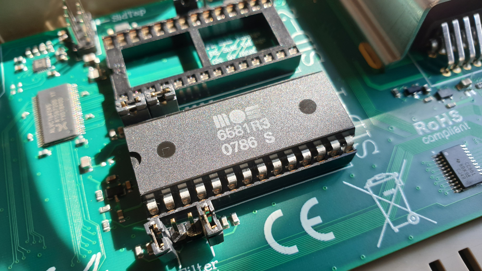
Insides! From left to right: Battery (for realtime clock, for file-system timestamps, maybe more?) my FSF welcome gift USB stick (64 MiB seemed appropriate), WiFi (unsupport at the moment), then we move to the middle, up: RCA for analog SID ouput, SID-1 populated by heatsinked MOS6581R3, LED, keyboard connectors.
It's important to set voltage and filter jumpers correctly before installing the SID chip, as the 6581 and 8580 take different voltage and require different filtering. The default is 8580, I suspect that's because this chip takes the lower voltage, so chances of frying a chip on oversight are smaller.
The keyboard connector just works, there is a key pin missing, so you need to be quite an idiot to install this in the wrong orientation.
Let me get this off my chest: I'm perplexed as to how I managed to do this damn sexy macro with my phone, but I couldn't manage anything like it with my DSLR.. Anyhow, that's how it looked before I defiled it with thermal compound and super-attack glue.
The SID chip was heatsinked as this IS a 12 volt chip with some amount of leak current and a reputation for hotness (they can be burning hot to the touch), so I found an old heatsink designed memory chips, applied some thermal compound to the middle, and superglue on either side, and pressed it quite firmly onto the chip (do this before installing the board, as to avoid flexing it!) so that the thermal compound squeezed out the sides and ensures good heat transfer.
The board will output SID audio via the commodore AV connector and over HDMI, but it also provides a tap for pure analog goodness, so, well, why not ;)
I switched the plug from the red to black color because it looks cooler, and decided to upload that, more detailed picture. See comparison between A/V connector and SIDtap output at the end of the page.
When the board is first powered up, a friendly instruction appears, explaining that no operation ROMs are yet installed, and how to install them. The procedure is very simple, acquire roms (from a c64 or the Interwebs), throw them on USB stick, plug USB stick into the U64 board, enter setup and point to the roms.
Re-flashing different roms is ultra simple, the normal file-browser will ask you what to do if you press enter on any .bin file.
Notes
* The initial configuration has the HDMI output set to DVI mode, this does not support audio, so if your audio is not working, that's probably why. Also not that not all monitors support DVI over HDMI (I've bee told, mine did, so well..).
* After multiple successfull runs, a demo (Tsunami by Booze Design) would freeze after SID model selection, this behaviour began after I experimented with a the video output (building custom cable), in the end, the problem was fixed by re-flashing the firmware, which was _VERY_ simpe and probably the best upgrade experience I've had the past 2 years on any platform: Download file, put on usb, select in filemanager, super nice! AND it fixed my problem.
* I've not yet found a way to swap joystick ports virtually, the Final Cartridge III supports joyswap, but it does not seem to working when I do it on the Ultimate64 device during gameplay (which is the point in time where you know if you need it), I hope there will be "native" support for that in the future.
* The video DIN connector IS compatible with original commodore cables, I've no idea what kind of DIN connectors I got from china, but there seems to be different pitches even with same number of pins, so DON'T FORCE THE DIN CONNECTOR!
* You can control some stuff over TELNET over the ethernet card, kind of fun, at least I can start SIDs playing with it, but it's not good for that much in general. There is some FTP support: The device can NOT access an FTP server, but acts as one, allowing you to browse the Ultimate-64 from another PC, that's a bit upsides-down, it'd prefer to access file-storage from the U64, but hey, it's something, however, the D64 disk images that I PUT to the U64 were corrupted on arrival, so there's some work there.
* The WiFi is currently not usable, but the networking aspects of this board is not it's main attraction, and there are probably still work going on there.
* T64 files: They should be "entered" and then the prg can be selected and started"
* TAP files: They can be "run" or "started" as tapes, and work as expected with the load command from basic, they load like real tapes, excellent!
* GIF images made with following commands: ffmpeg -y -hide_banner -i "1.mp4" -filter:v "crop=$WIDTH:$HEIGHT:$X:$Y,fps=10,scale=320:-1:flags=lanczos" frms/frame%03d.png and then convert -loop 0 frms/* out.gif
Network
The network card is available to the C64, and is used by at least UltimateTerm V2.0. UltimateTerm does require the "command channel" to be enabled, and any inserted cartridge to be disconnected (physically or virtually!) this is annoying. I'd much prefer to be able to have my favourite cartridge available alongside terminal action, I don't know if this is caused by the way UT or the network card is implemented.
WiFi Modem
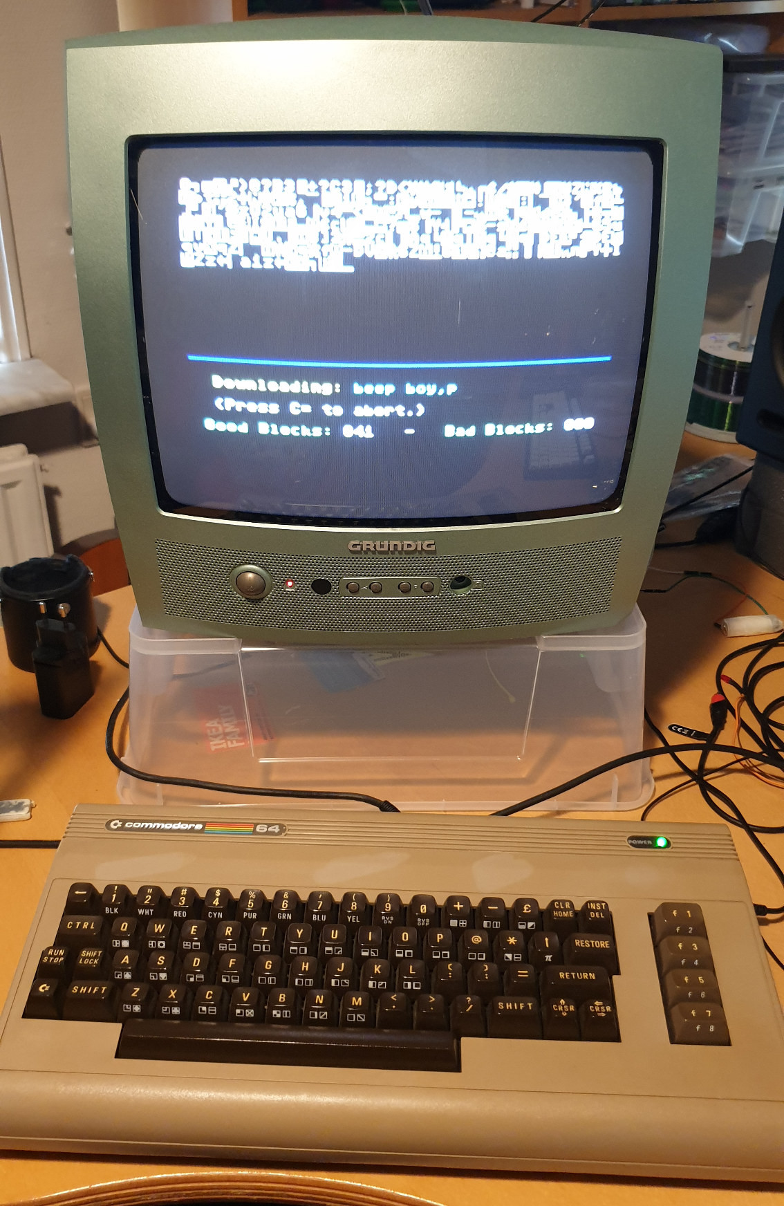
Downloading some warez from a BBS with the punter protocol, "Set your terminal to receive a file!.
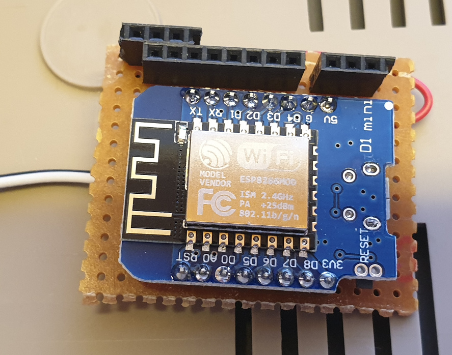
2019-08-11I've had enough fun visisting various BBS services that I decided I need a modem that's compatible with FinalCartridge3 and won't require me to take that out or change any settings which may cause incompatibilities with other software. So I built a modem for the internal user-port with an ESP8266 board, called "Wemos D1 Mini". The build was fairly simple, I did not write the software, but followed this guide: https://1200baud.wordpress.com/2017/03/04/build-your-own-9600-baud-c64-wifi-modem-for-20/. I changed the firmware a bit before I got it working on the Wemos mini D1, but that may just have been me.. It works now so I'm not going to invesgitage further.
The firmware supports a button for resetting to 300 baud, I don't think I'll need to do that often, so that button is internal.
Installed in the Ultimate 64
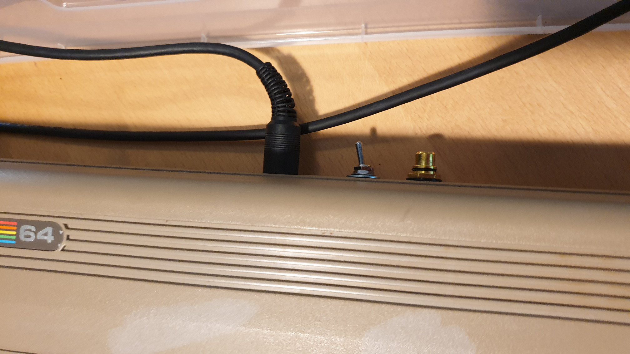
Strangely, when I boot the Ultmate64, the ESP locks up, maybe in flash mode, however, if it is turned on AFTER the U64, it works fine. This is not an issue however, as I really want to be able to turn it off when it's not in use, as the ESP does generate a bit of heat and, why have stuff turned on when it's not in use? So I mounted a switch on the +5 wire.
The two grey wires is +5 to and from the switch, so the modem can be turned on and off.
The other grey wire goes to the blue chip in the RGB LED, so that activity is shown in the power LED.
Wishlist
* Joyswap! It'd be super nice to have in the F5 menu, or maybe Shift+F3 ? This is by far my biggest wish!
* Make filebrowser access PC over FTP/HTTP or samba or even just a dedicated server program (like ide64servd).
* Support both common anode AND common cathode LEDs
Network Video
The new firmware 3.5a supports streaming the VIC video over ethernet! That's super cool and useful, especially for streaming! I wrote a viewer for it, it can be used for livestreaming together with OBS.
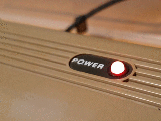
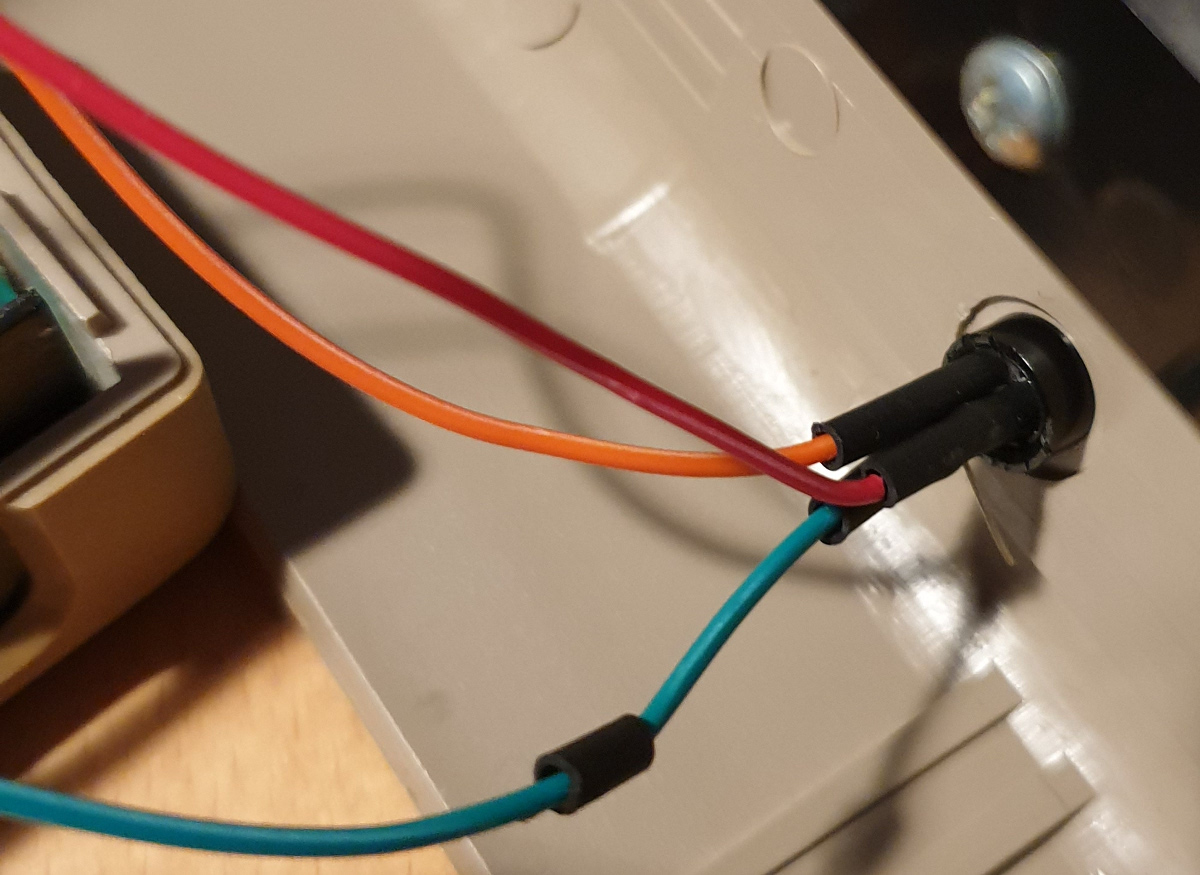
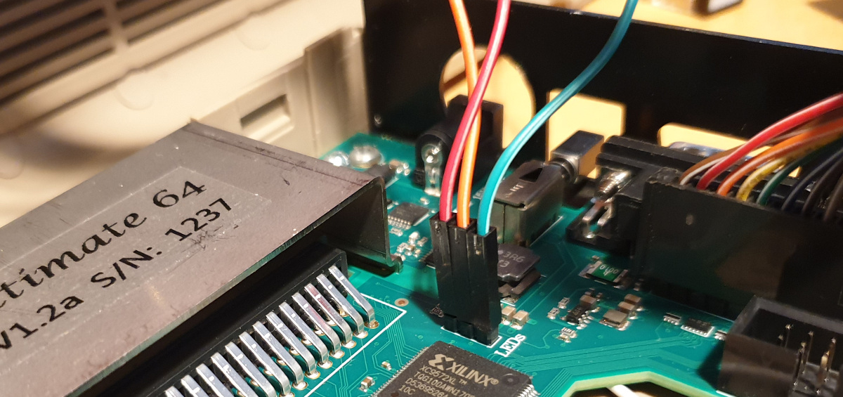
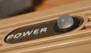
I replaced the original red LED (will sell as ultra rare(tm) for 1000 usd on ebay later) with a milky clear RGB common kathode model. NOTE: To remove the LED, you need to pull the plastic ring on the backside away, I used a small flat screw driver to help lift it.. After doing this, the LED can be pushed down, I needed to help the taps let go a bit with my fingers, be careful, that old plastic is probably brittle. After pushing the new LED back in, simply press the ring back, it is then securely fit in place!
The U64 has a 3 pin header for the power LED, pin 2 is GND, pins 1 and 3 can be configured from the settings menu, I set "pin 1 = Off on any activity, pin 3=On on any activity", this way, the original RED color is shown when the machine is on and doing nothing, but the LED becomes green when I'm doing stuff on USB or when the disk drive loads (or blinks from error, such as file not found).
Resistors are soldered to the red and green LED pins. The resistors are under the heatshrink.
Orange is GND (the common cathode), but at least red is red led and green is green led.
This is the power-up sequence. The camera overexposed it, it is the correct brightness when viewed in real life.
The RGB led I used was way to bright with only the onboard resistors, and I added a 10k resistor to the green pin and a 4k resistor to the red pin to get the desired brightness.
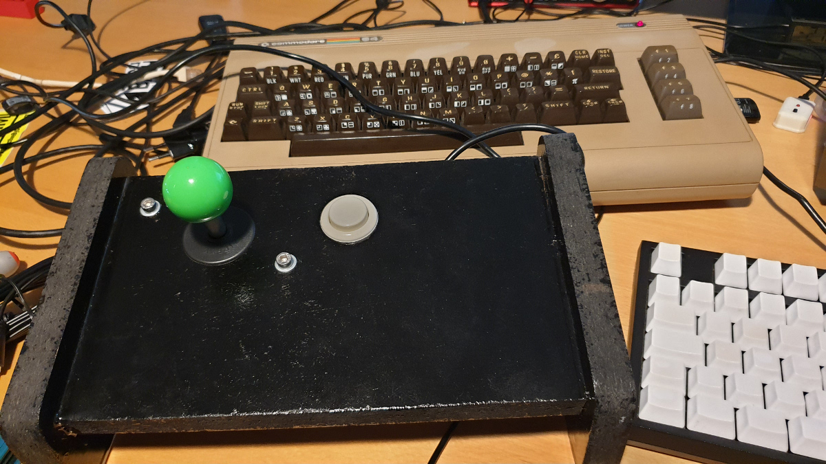
Joystick
I built two identical sticks years ago, using surplus arcade joysticks and buttons.
Stick and button positions stolen from arcade cabinet.
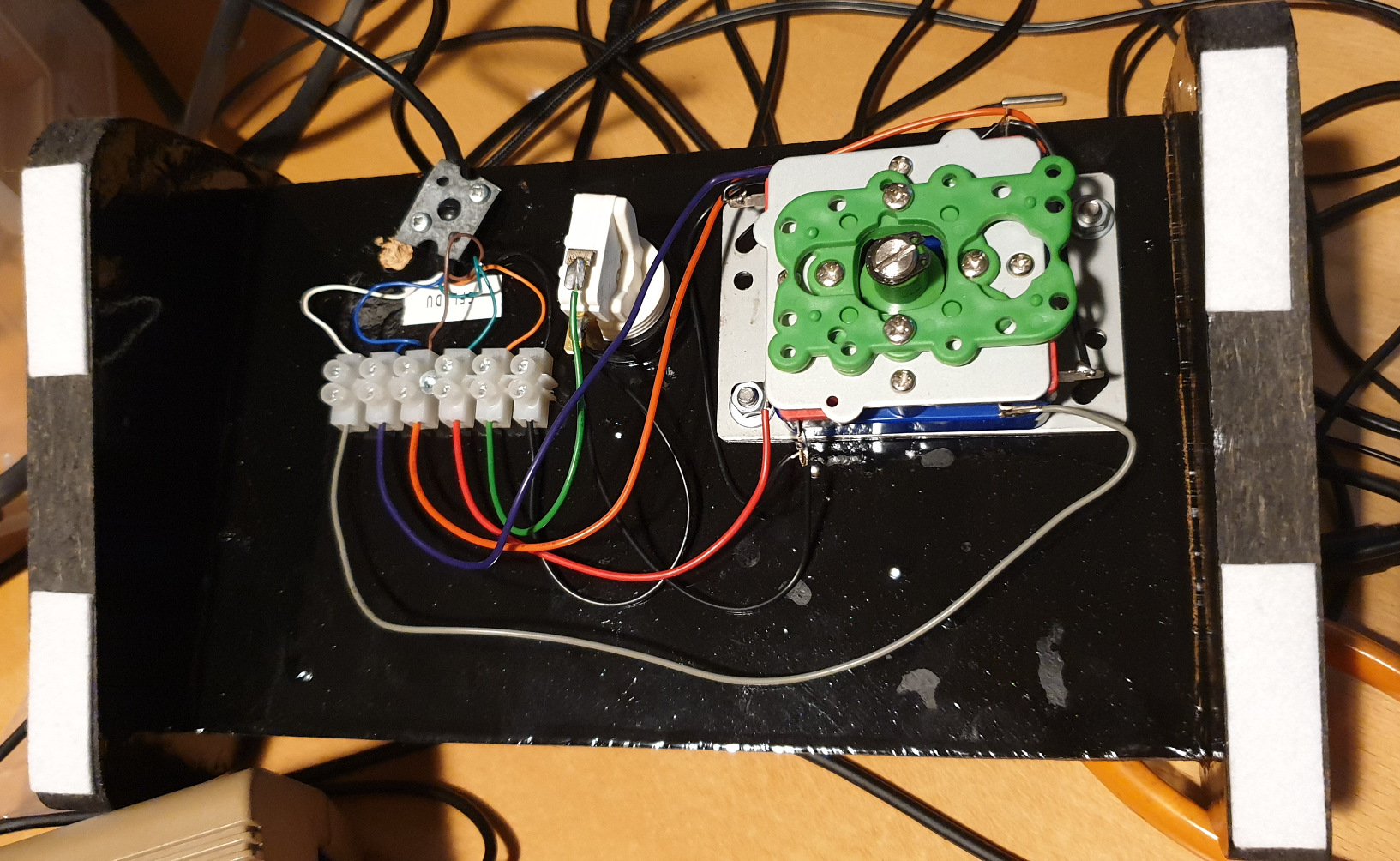
The cable was taken from a broken C64 joystick, I decided not to do too much about the backside, it's serviceable! Yes, I soldered the switches, they can be opened and serviced without desoldering.
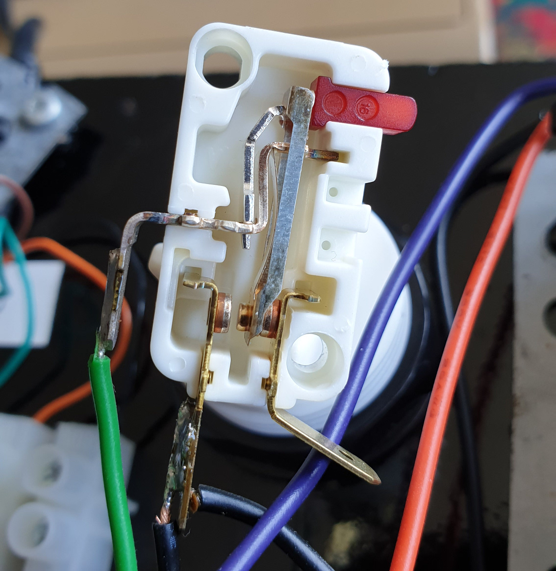
I had one of the switches behave badly, it wouldn't register every time I pressed. Luckily, microswitches are serviceable parts! Just open it up, clean with a solvent (I used isopropanol).
Removing the bottom part of the switch is trivial as it has no mechanical connection to the top part, and that gives plenty of room for a q-tip cleaning of both contacts.
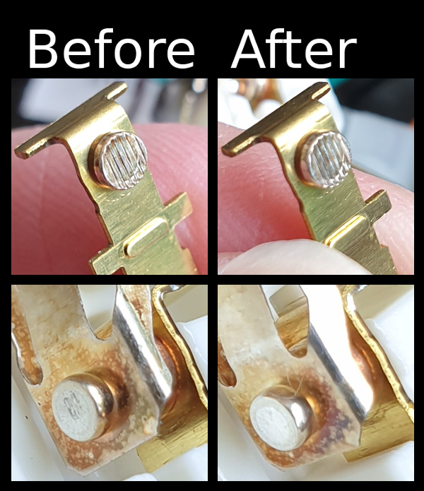
Check the difference! Now the switch works perfectly!
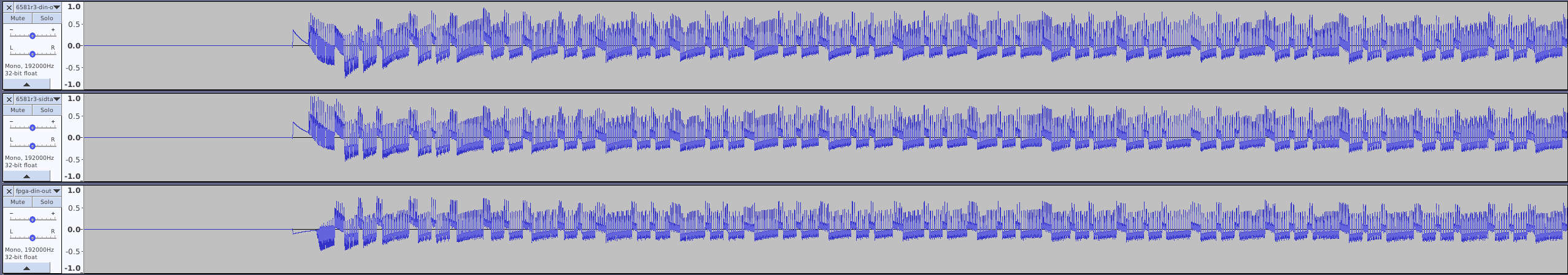
Audio in detail
I'm not an audiophile, but I do appreciate sound, and as such, I was curious as to the difference between the built-in sid emulation/fpga implementation and the SID chip I had.
The test:
3 runs of audio with cable from the commodore din ouput for both 6581r3 and FPGA (same attenuation level)
3 runs of audio with cable from sid-tap for 6581r1 (FPGA does not output to this)
There were no signifigant difference between the runs, and so only the first run was kept: 1 for fpga via din, 1 for sid via din and 1 for sid via sidtap
Audio recorded in 192k on a scarlett 2i4, play was started after a few seconds (to capture line-noise)
NOTE: I did not capture output from sid tap and din simultaneously, this might be a mistake (see picture 2), but if I'd done that, I'd have been worried if the cable or input may be different. Instead I'm worried that the runs may have executed differently.. Bad science!
Each track was normalized to -0.5db to make comparison easier, but not DC offset corrected.
By my own listening, I could not hear any difference between the sidtap and the din-output, however, audacity did show slighty more noise (about -53db) in silence when the SID was used over din (the board sampling and picking up or introducing noise?). I did hear a difference between the FPGA and the SID, however, it is slight, and I suspect the same difference could be found between two SID chips of the same revision. But to my ear, the SID does have more depth in the bass, it's warmer, I hate to say this, because I don't believe in analog warmth, especially not since I've gone and digitized it and am listening to a digital playback, but, nevertheless, the sound is different.. Which is more "correct"? I don't know, but the real sid does sound slightly nicer to me.. headfi effect?
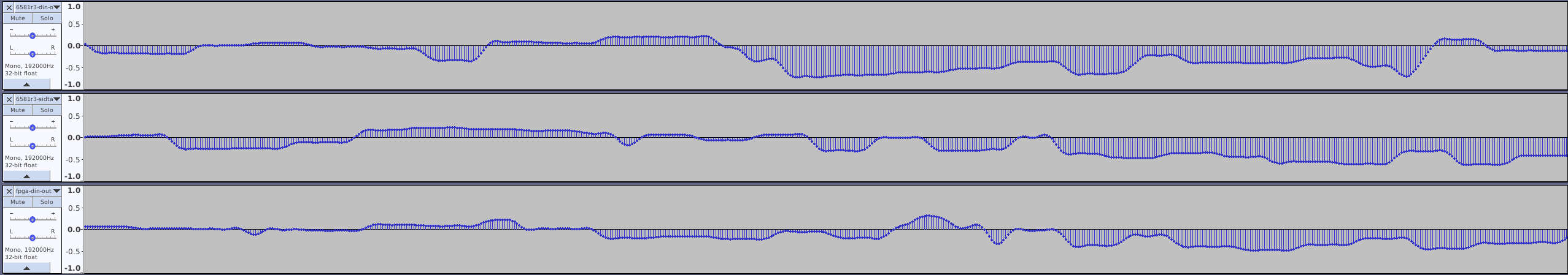
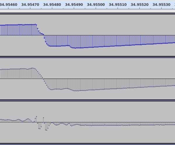
Top: SID over DIN, Mid: Sid over SID tap, Bottom: FPGA.
The beginning is indeed strange, I don't know what sound this actually is, maybe it'ts the output from some initialization.
This is strange, part of the waveform seems to be missing from the sid via tap run, I can't HEAR the difference, but it's clearly there, I wonder if this is some artifact of the SID not behaving 100% the same from run to run..
Some later parts seem to be out of sync when zoomed far down, but they SOUND like they're in sync..
Other, even later parts seem to be in sync, though, zooming down enough reveals that they're off as well, this drift may be from the U64, or it may be my sound recording..
Download the tracks and see/hear for yourself..
If you're super interested, and want to download 328 MiB, extract 800 MiB and have a closer look at the files, I've packaged the recording in an Audacity project u64-fpga-vs-sid.tar.xz (328 MiB)
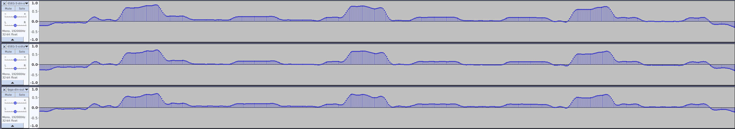
SID Tap vs DIN output
I decided to do one more test: Connect both the DIN output and the SID Tap output to the scarlett and record the same playback to see how they compare. I found differences that are impressively small.
The first finding was that there is a small ( 0.5 millisecond ) delay on the DIN audio (bottom), I verified this by switching recording cables and inputs. I suspect the delay is aligned with the video output, but I've got no way of verifying this. Such a small delay is not important.
The second finding was that there is that the output does not appear untouched through the DIN, I suspect this is due to resampling by the board (as the stream is digitized for HDMI and I suspect the same pathway is used for DIN output, to make it work both with real SID and ultisid. These differences are visible in Audacity, but I've not been able to hear them at all. It looks like the DIN output is "softer", and does some undershooting and overshooting, I'm not enough into DSP stuff to say why, but again, I can't hear the difference.. You can try yourself if you want to in this Audacity project: TAPvsDIN.tar.xz (150 MiB) NOTE: I did NOT normalize these as that results in enough quantization that comparing the waveforms becomes difficult, but I adjusted the gain on the scarlett, there is quite a lot more signal on the TAP than on the DIN. (I'd reckon I've turned 1/5th more gain on the DIN input)
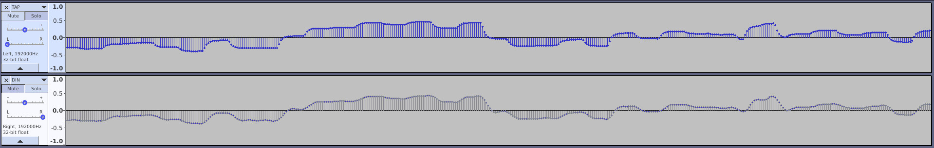
Here, I aligned the waveforms, normalized them, inverted one, mixed them into stereo and mixed that into mono and normalized that waveform up from silence, the resulting waveform is the exaggerated difference, quite enough to hear a lo-fi version of the tune when played back
Last words
This is such an awesome board! It's not only great fun, it's technically very impressive! The differences I show are magnified a lot, and only serves as testament to how well things have been done! Go buy one!