... or how to build a 7 segment LED display the hard way!
... or maybe, how to make 3D printed enclosures with integrated display!
... or how to make a reaction timer? ok, I'm done.. This thing was done entirely because I was curious if I'd be able to figure out how to build my own 7 segment numerical displays.I found that I was it was satisfying, fun and I learnt something too, excellent!
Motivation
I've always liked displays of different sorts, and 7 segment displays are probably the next simplest thing from the humble LED, actually, they can be built with LEDs, and many commercial
models are "just" a piece of plastic with the right shapes, lightguides and LEDs (all very integrated). So I thought that I'd try figure out how to build and drive my own, from scratch, more or less, I mean, I
didn't build the LEDs, or the microcontroller or the hotglue gun or the 3D printer, so I don't know what "from scratch mean", anyway, I wanted to try and make my own instead of chosing the
cheap, quick and easy solution of buying professionally manufactured ones, I just wanted to see if I could do it, and I think I could.
Anatomy
A 7 segment display is made up of, well, 7 segments.. of such a shape and arrangement that when they are all "on", they form the number 8. Now, draw the number 8 using only straight disconnected lined, and see how you can, using those 7 lines, discover every other possible number! For example, remove a the bottom lefthand line, and your 8 becomes a 9... Sorry.. Anyway, one cool way of making a 7 segment display would be to produce LEDs with the shape of the lines, then arrange them in the right pattern and cover their sides up.. That'd require some interesting LEDs.. Another way of making a 7 segment LED display could be to have the 7 shapes be cavities in an opaque material (like plastic), then have LEDs at the bottom of those cavities and fill it with a semitransparent, diffuse material
(like epoxy or hotglue) to create a the right shape.
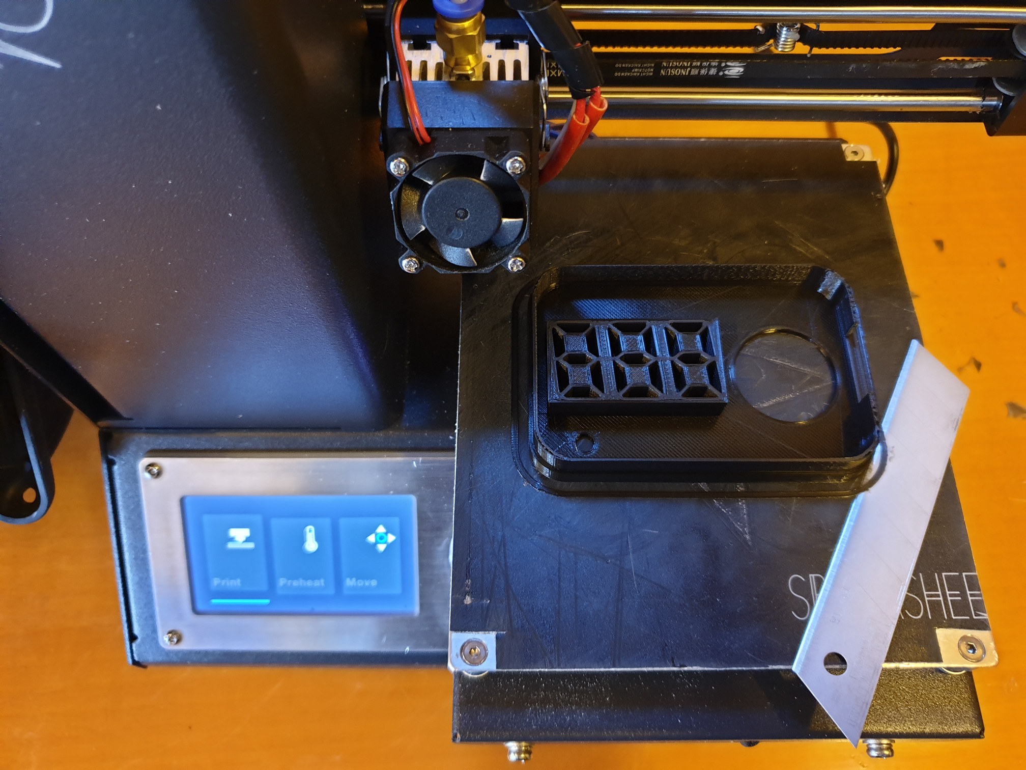
That's the approach I went with, I thought it'd be super cool to be able to 3D print a box where the segment display was actually a part of the box itself instead of just leaving a hole for
a display to stick through!
So,, I 3D print a box where the segments are cavities, 3 mm wide, because.. 3mm leds.. and then fill them with hotglue and stick in the LEDs, easy!
First try
The first try had two minor issues, I had chosen the outer segments to have a more narrow design, which didn't turn out to look good, and I had forgotten to remove a bit of material, preventing the nut that goes on the arcade button from being flush with the bottom of the plate, minor things, but still, I started printing another (fixed) piece and use this one to find out how to actually fill the glue into the cavity and mount the LEDs, and see how the light would travel through the hotglue.
LEDs fit fine enough, next image, i try filling from the outside, but that proves difficult to control, and I melt some of the plate with the hot end of the glue gun.
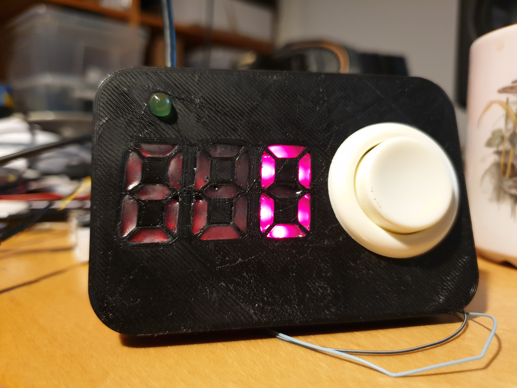
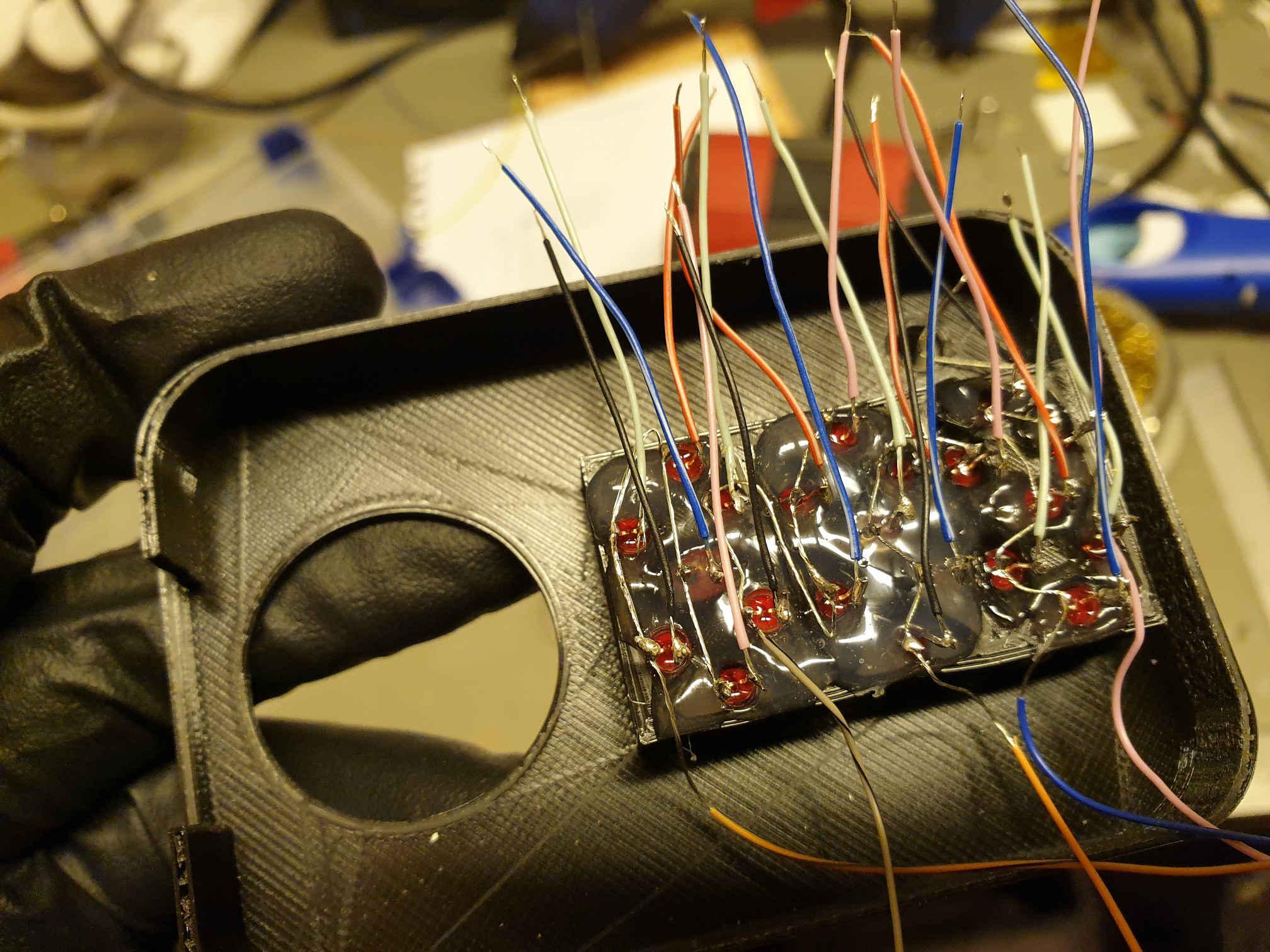
The second try, I filled from the backside, against the shiny side of kapton tape. The hotglue still sticks very well to the kapton, but it is possible to remove it again, and fix up the surface by heating it with the flame of a gas ligther. I used a green LED here, and it looked beautiful, unfortunately, I didn't have 21 3mm LEDs so I went with red, this was the best hotglue pour, I'm not sure why, but the rest didn't turn out as nice.
Mechanical things to it
The most difficult part for me, was to keep tract of how to wire up the thing, after connecting the 5 cathodes lines, I decided that routing wire around for the anodes lines would be too difficult, so I soldered individual wires to the anodes and connected them at the MCU instead.
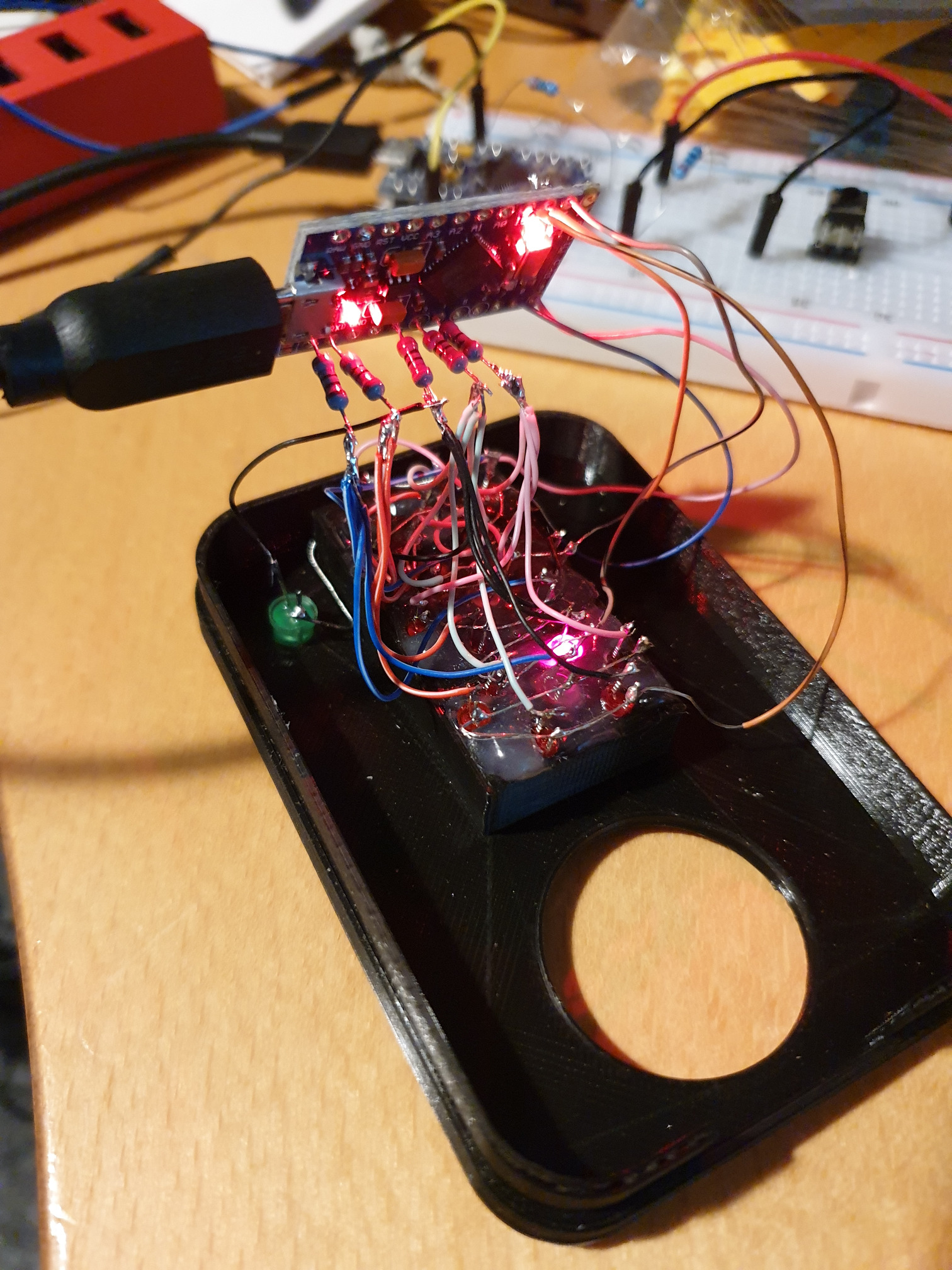
After writing a test program to check that all segments could light up individually (no shorts, no opens), I gave it an extra shot of hotglue. I used a fat piece of copper wire between the switch and the GND pin on the MCU to help support the board as it was hanging by the wires.. The board has two LEDs on it which are quite bright and caused a noticable amount of light to go through unlit
segments, so I covered those up with black electrical tape.
Theory of operation
I wanted to be able to display at least 3 digits, that's 7x3=21 individual segments. One way of controlling these would be to wire 21 leds in with 21 resistors to 21 MCU pins.
However, that's a waste of resistors, and I don't think my MCU (board) even has 21 pins (I just counted it has 18), so that's unpractical. One approach could be to charlieplex the LEDs, that
could be done with only 6 pins! However, as I've got no experience with even traditional multiplexing, I decided that a traditional X,Y multiplexing would be sufficiently challenging to construct
and program.
The idea is to have 5 pins source and another 5 pins sink. Arranged in a 5x5 grid, this gives us 25 individually addressable LEDs, and we only need to use 5 resistors. In order for a LED to
light up, a voltage difference must be present across it, so, in other words, if there is voltage at the anode and no/less voltage at the cathode, current will flow through the LED, making it
emit light. If the same voltage (relative to some ground) was present at both ends of the LED, no current would flow through it, and it would not light up.
preCAD 0.1:

Matrix (x=led)

	1 2 3 4 5
	| | | | |
	x-x-x-x-x-[280R]- A
	| | | | |
	x-x-x-x-x-[280R]- B
	| | | | |
	x-x-x-x-x-[280R]- C
	| | | | |
	x-x-x-x-x-[280R]- D
	| | | | |
	x-x-x-x-x-[280R]- E


Zoom in on led (A=Anode, C=Cathode, #=wire)

	Col 1 pin on MCU
	   #
	/--#-----\
	|  #     |
	|  A  C####### (Cathode of next rowA LED) ### Row A pin on MCU
	|  #     |
	\--#-----/
           #
	(Anode of next col1 LED)
As I might have failed to demonstrate, the idea is that the LEDs in Column 1 will have their Anodes connected together, the LEDs in Column 2 their Anodes connected together, and so on, just as the LEDS on row A will have their Cathodes connected together and so on. This means that no LED will share both cathode and anode with a led on the same column or row. So, if we now have 5 volt on a column, for example, column 1, all on that column could be turned on, if a current sink was available at its cathode.
This approach does have a disadvantage: One could not turn on, at the same time both leds 1A and 2B, that would also light up 1B and 2A. Low-end keyboards use a similar concept for detecting which key has been pressed, and that is why pressing multiple keys at once may produce "ghosting" or, keys not being pressed down detected instead of the correct keys (good keyboards do not have this problem). So back to the stoary: With the LED matrix, we can only have one LED (or segment) on at a time, so, we switch between them rapidly (I chose an "on" time of 100 microseconds for each, 21x100=2.1 ms per "draw", produces a faint blinking effect when one moves their eye rapidly over the display in a pitch black room, but which is normally unnoticable), it is so fast that the "super slow" camera function on my phone will artifact the CMOS scanning rather than showing individual segments turning on one at a time. So, that's fast enough.
I chose to implement it using two MCU ports, so that I could store the information about which pins should be high or low for each segment in a byte for each port, that is 2 bytes of memory for each segment, or 42 bytes of data, a bitpattern where each bit corrosponds to the pin on the port. This information could be calculated, but for simplicity I chose to store it in an array, this would
also allow me to do a software fix if I happened to wrongly wire up a row or column, but that didn't happen (much to my surprise).
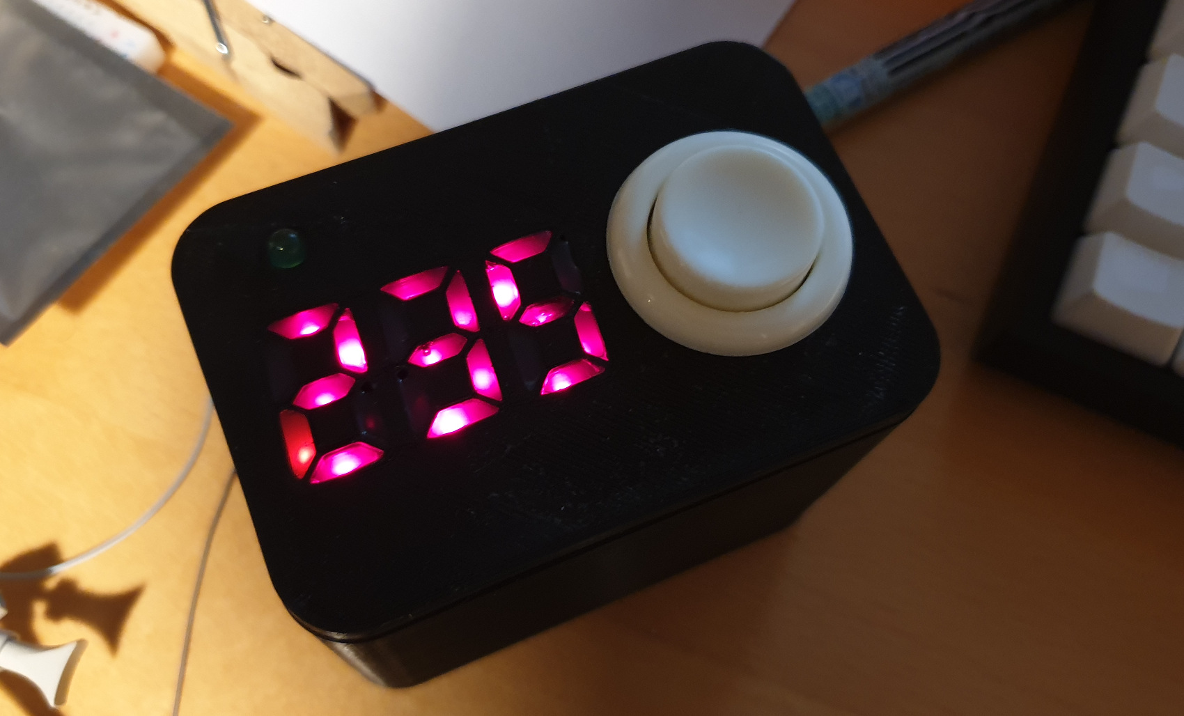
Application
The application is super simple: Measure your reaction time by waiting for a LED to light up, when it does, press the button, your reaction time is measured as the amount of time, in milliseconds, it took from the LED to light up to the button to be pressed. If the reaction time is over 1 second, I can't display it, so I'm calling that invalid. If the button is pressed before the LED lights up, it's also invalid.
This is not the most exiting application, but kind of a fun thing to have on your desk anyhow, especially if you're the type who enjoys first person shooting games..
Schematic
Sorry, not going to draw that.. The lower bits (starting from 1)of PORTD are connected to the 280 ohm resistors, then to the anode lines of the LEDs. The lower bits (starting from 2) of PORTB is connected to the cathode lines of the LEDs. One side of the switch is connected to GND, the other side to A2.
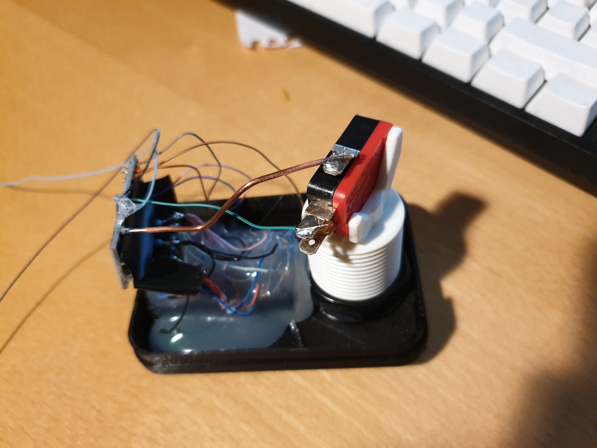
Case
The case was written in OpenSCAD. There are two parts, a box that is deep enough to hold the arcade button and a frontplate with a hole for the button and the actual segment part. I based
it an existing library for generating parametrized 7 segment display shapes, you need that library if you want to print my box.
There are two modules, lid and case, and they are both enabled at the very last line of the file. I've done this so I can render an STL for each, and print them seperately (my printer can do 12x12x12 cm but I prefer printing in two takes instead of pushing to the edge of the bed).
There's only one button, these are the states and their meaning.
LED blinks: Press button to start test
Count down ( 3, 2, 1 ): Prepare to press the button as soon as LED turns on
LED On: Press button
Number: mS elapsed between LED turning on and button press, press again to continue
Falling bars: Too slow, button not pressed within 1 second
Rising bars: Too quick, button pressed while LED still off
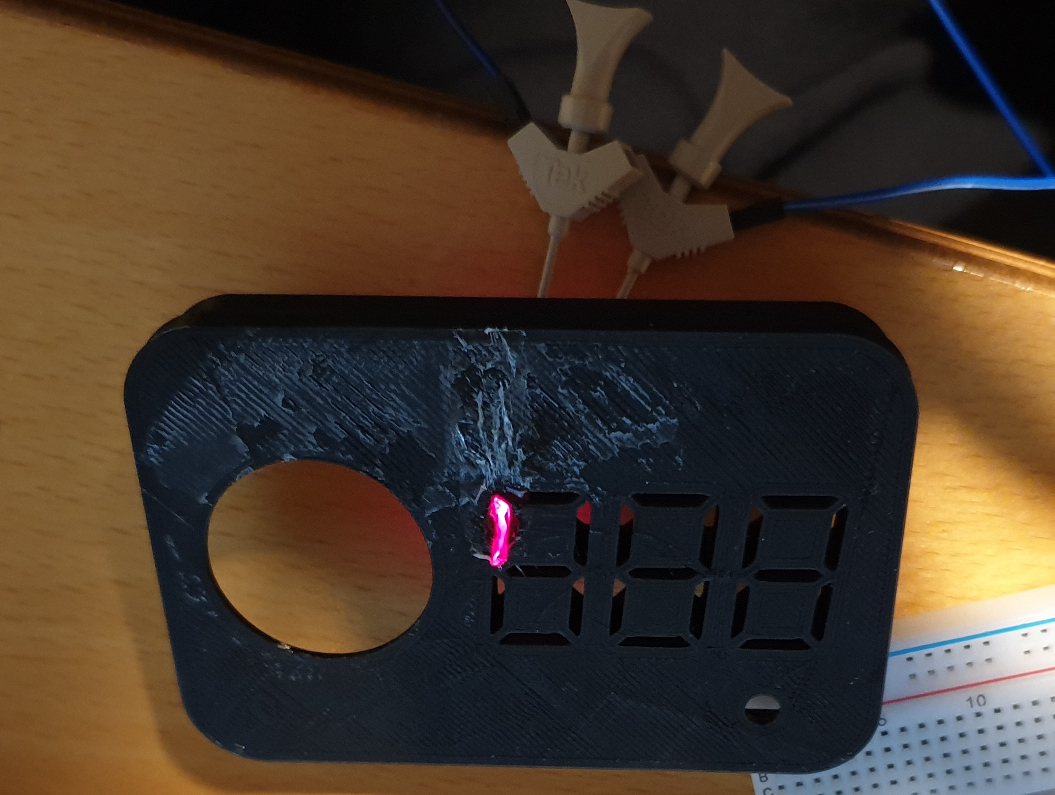
How precise is it?
It should be +/- 1 ms. I wrote a small program to test it, by observing the LED via a photoresistor and pressing the button (by sinking). It consistently returns 2 ms, I suspect this is the lag of the photoresistor, but I'm not going to investigate it, as 2 ms is quite below noise level when measuring human reactions.
Practicality
So, is it practical to build cases with integrated displays? Yes!, though not the way I chose to do it here. Results are inconsistent, assembly is difficult and construction is unreliable. However, those challenges can be overcomed. Using a better material than hotglue, for example 3D printing the segment shapes in clear or white material or using a thin epoxy resin or similar would work a lot better. As for LED placement, wireing, assembly and reliability, laying out a PCB, including mount holes that fit to the case would solve that problem, a solution which I may try in the future, it would also allow me to use 2 SMD leds per segment, allowing brigther and more evently lit segments.
The software is not too cumbersome, but using either serial shift registers or an actual dedicated segment driver would made it even easier to use, especially for situations where the MCU can't afford to spend so much time drawing the display.
All in all, I've learnt a lot, and believe this approach can become practical for future projects in a more refined form.